Apparatus for regulating the gas/air ration for a pre-mixing combustion device

a combustion device and apparatus technology, applied in the direction of fuel supply apparatus, combustion process, lighting and heating apparatus, etc., can solve the problems of affecting the gas quality, air pressure and combustion air temperature, and the system with electronic coupling is slower to stabilise control as regards changes, and achieves the effect of reducing the gas/air ratio, reducing the cost of gas/air conversion, and increasing the speed of air entering the mixing chamber

Active Publication Date: 2006-01-31
HOVAL
View PDF6 Cites 9 Cited by
  • Summary
  • Abstract
  • Description
  • Claims
  • Application Information

AI Technical Summary

Benefits of technology

[0016]The regulator constitutes the pneumatic coupling of the system and the sensor supplies the signal which enables the effects of the variation in the gas quality, the air pressure and the combustion air temperature to be compensated for. The conical member, which is preferably actuable by a linear motor, moves in dependence on this signal and travels to a greater or lesser depth into the nozzle connected to the air conduit. It can thus be ensured in an extremely simple manner that the combustion device always operates with an optimal gas / air ratio.
[0031]It has proved to be particularly advantageous to provide the conical member with an angle of less than 30°. This angle enables very sensitive adjustment of the conical member and thus very sensitive regulation. However, conical members with an angle of more than 30° are also possible under certain circumstances.

Problems solved by technology

Influence parameters, such as gas quality, air pressure and combustion air temperature, can, however, not be compensated for by these systems by control techniques and necessitate an adjustment to the installations.
Furthermore, systems with a pneumatic coupling become imprecise with a large modulation range in the lower power range, particularly after a relatively long period of operation.
These systems with an electronic coupling are slower to stabilise control as regards changes in the air volume as regards the control.
The sensors which are used are sensitive and have a limited surface life.

Method used


Image

  • Apparatus for regulating the gas/air ration for a pre-mixing combustion device
  • Apparatus for regulating the gas/air ration for a pre-mixing combustion device

Examples


Embodiment Construction

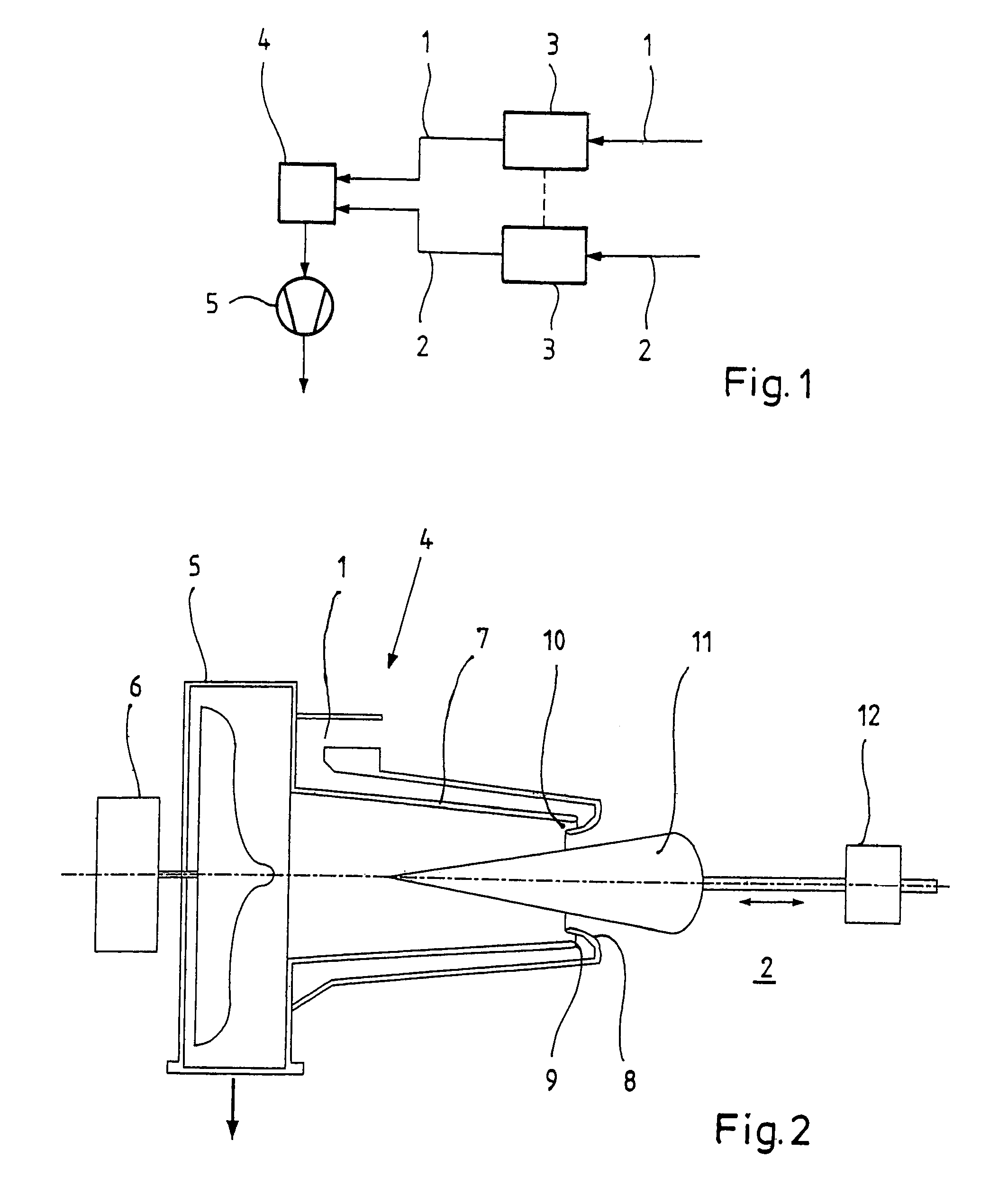
[0035]The apparatus shown in FIG. 1 has a gas conduit 1 and an air conduit 2. Operating between the two conduits is a pneumatic regulator 3, which controls the pressure in the gas conduit 1 in dependence on the pressure in the air conduit 2. The gas conduit 1 and the air conduit 2 both communicate with a mixing device 4. Arranged downstream of the mixing device 4 is a fan 5, whose speed may be controlled and which conveys the mixture to a combustion device, which is not shown.

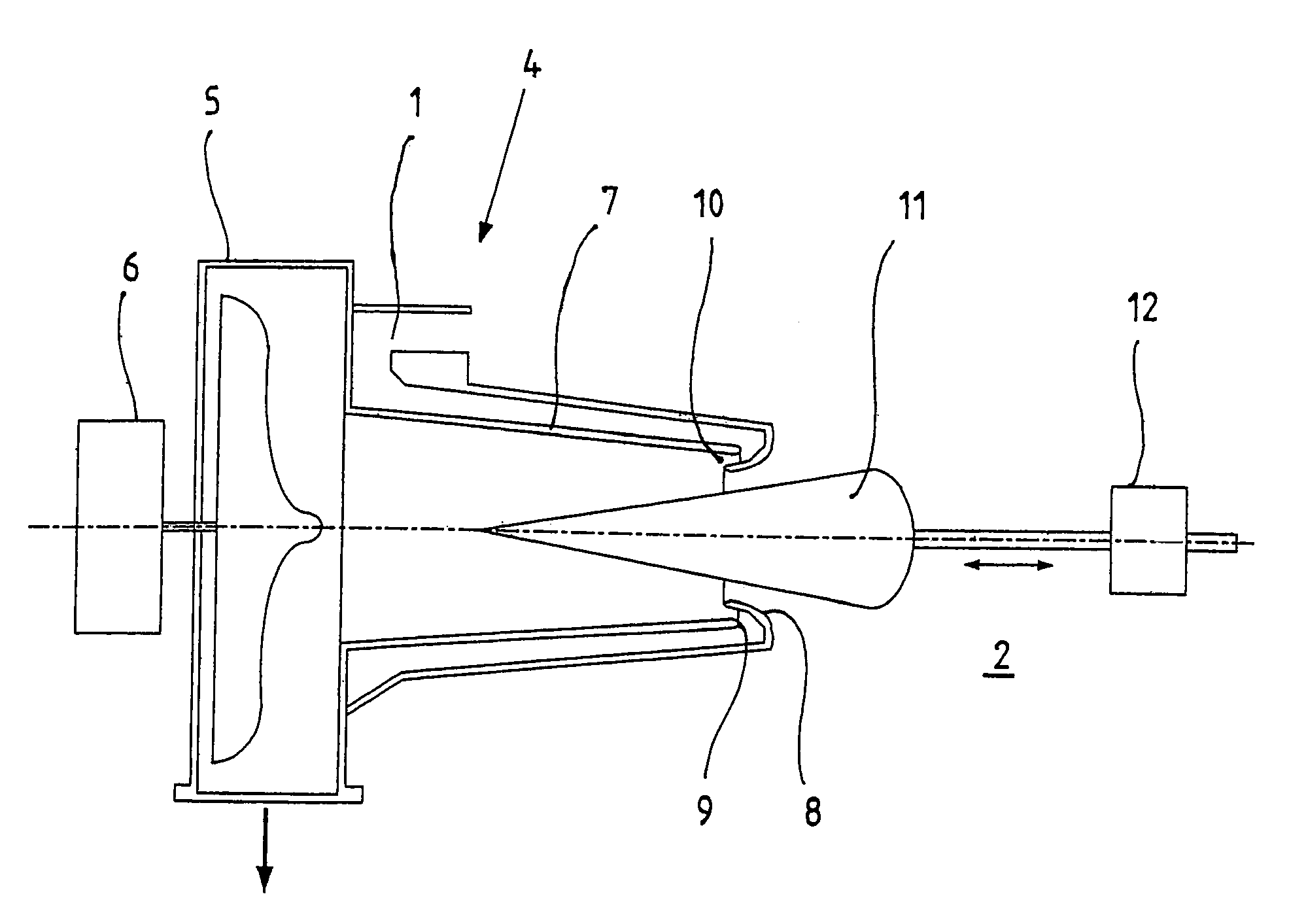
[0036]FIG. 2 shows in detail the construction of the mixing device 4, to which the fan 5 is directly connected. The latter is driven by a motor 6, whose speed may be controlled.

[0037]The mixing device 4 has a mixing chamber 7, which diverges from its inlet opening in the flow direction in the manner of a venturi nozzle. Extending into the inlet opening of the mixing chamber 7 is a nozzle 8, which is connected to the air conduit 2. The nozzle 8 defines, together with the edge 9 of the inlet opening of the mixing...


PUM


Abstract

The apparatus has a pneumatic controller, which controls the pressure in a gas conduit (1) in dependence on the pressure in an air conduit (2). Provided downstream of the regulator is a mixing device (4), which has a venturi-like mixing chamber (7). Extending into the inlet opening of the mixing chamber (7) is a nozzle (8), which is connected to the air conduit (2). Defined between the nozzle (8) and the edge (9) of the inlet opening of the mixing chamber (7) is an annular gap (10), which is connected to the gas conduit (1). Also operating in the air conduit (2) is a conical member (11) which is actuated by a linear motor (12). The mixture is withdrawn from the mixing chamber (7) by a fan (5), whose speed is controllable, and fed to the combustion device. The adjusting motor (12) for the conical member (11) operates in dependence on a signal from a sensor, which detects changes in the gas quality, the air pressure and / or the combustion air temperature. The cross-section of the nozzle (8) connected to the air conduit (2) is blocked to a greater or lesser extent in dependence thereon in order to superimpose the sensor regulation on the pneumatic regulation.

Description

BACKGROUND OF THE INVENTION[0001]The invention relates to an apparatus for regulating the gas / air ratio for a pre-mixing combustion device.[0002]In order to minimise the emission of pollutants and to optimise the efficiency of combustion devices, efforts are made to maintain the gas / air ratio at an optimal point.[0003]Systems with a pneumatic coupling and systems with an electronic coupling are known.[0004]In the case of systems with a pneumatic coupling, the volumetric flow of the gas is maintained in a constant ratio to the volumetric flow of the air. This is effected by means of a pressure-controlled regulator in the gas pathway. A pressure difference is used as the control pressure to regulate the gas volumetric flow in direct dependence on the induced volumetric flow of the air. The control pressure for the regulator is produced in a mixing device or at an orifice in the air pathway.[0005]The systems with a pneumatic coupling require no electrical or electronic components. Thei...

Claims


Application Information

Patent Timeline
Patent Type & Authority Patents(United States)
IPC IPC(8): F02M21/04F23D14/60F23D14/64F23N1/02
CPCF23D14/60F23N1/027F23D14/64
Inventor STROHLE, WERNER
Owner HOVAL
Why Eureka
Try Eureka