Valve

a valve and valve body technology, applied in the field of valves, can solve the problems of liquid being very corrosive, internal valves in constant contact with the liquid of the vessel, and sudden drop in pressure across the valv

Active Publication Date: 2006-01-31
INFERNO MFG CORP
View PDF12 Cites 15 Cited by
  • Summary
  • Abstract
  • Description
  • Claims
  • Application Information

AI Technical Summary

Benefits of technology

[0014]It is desirable to provide a valve that protects the threads of the valve stem from the corrosive effects of vessel fluids and that protects the valve stem from potential damage. By locating the valve stem packing between the liquid in a valve unit and the stem operating threads, problems associated with corrosion swelling and the collection of suspende

Problems solved by technology

Gage glass breakage will result in a sudden drop in pressure across the gage valve, which seats the safety ball.
A problem common to standard valves is the fact that internals of the valves are in constant contact with the liquid of the vessel.
The liquid can be very corrosive and may contain suspended particles.
Since the valves are normally open, swelling associated with corrosion and/or suspended particles tend to collect and pack in the stem thread area, which can cause the valve to “freeze up” and become impossible to close.
However, such solutions have created additional problems by exposing the stem threads to the surrounding environment, which can be problematic.
For example, an inadvertent blow to the stem can cause bruising or bending of the stem, making the valve difficult or impossible to close.
Additionally, dirt and other debris are attracted to lubricants that are used on the threads and this may result in difficulty operating the valve.
The bolted bonnet requires an additional seal, which adds to manufacturing and maintenance costs.
A drawback associated with such needle valves is that the needle valves employ a bonnet that is threaded externally to fit internal threads in the valve body.
The non-intuitive aspect of first being required to loosen part of the valve before compressing of the packing is a disadvantage associated with this valve.
Another design weakness associated with using a rotating bonnet on a needle valve is revealed when a jam nut is left in a loosened condition, e.g.,

Method used


Image

  • Valve
  • Valve
  • Valve

Examples


Embodiment Construction

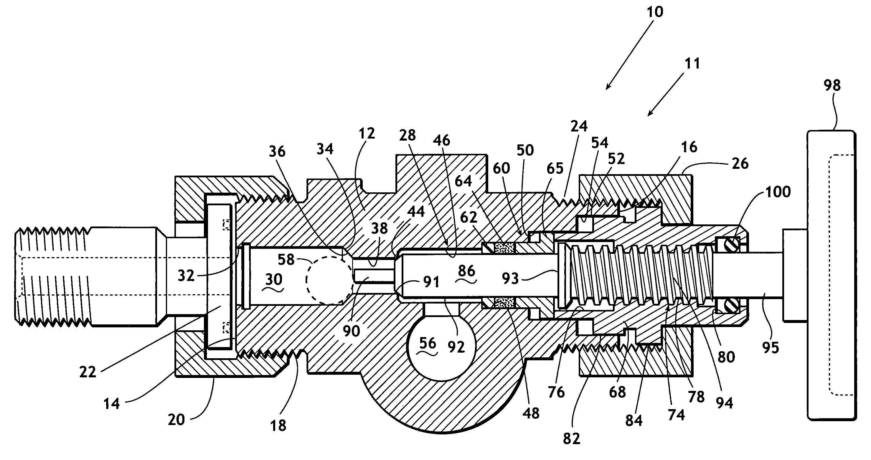
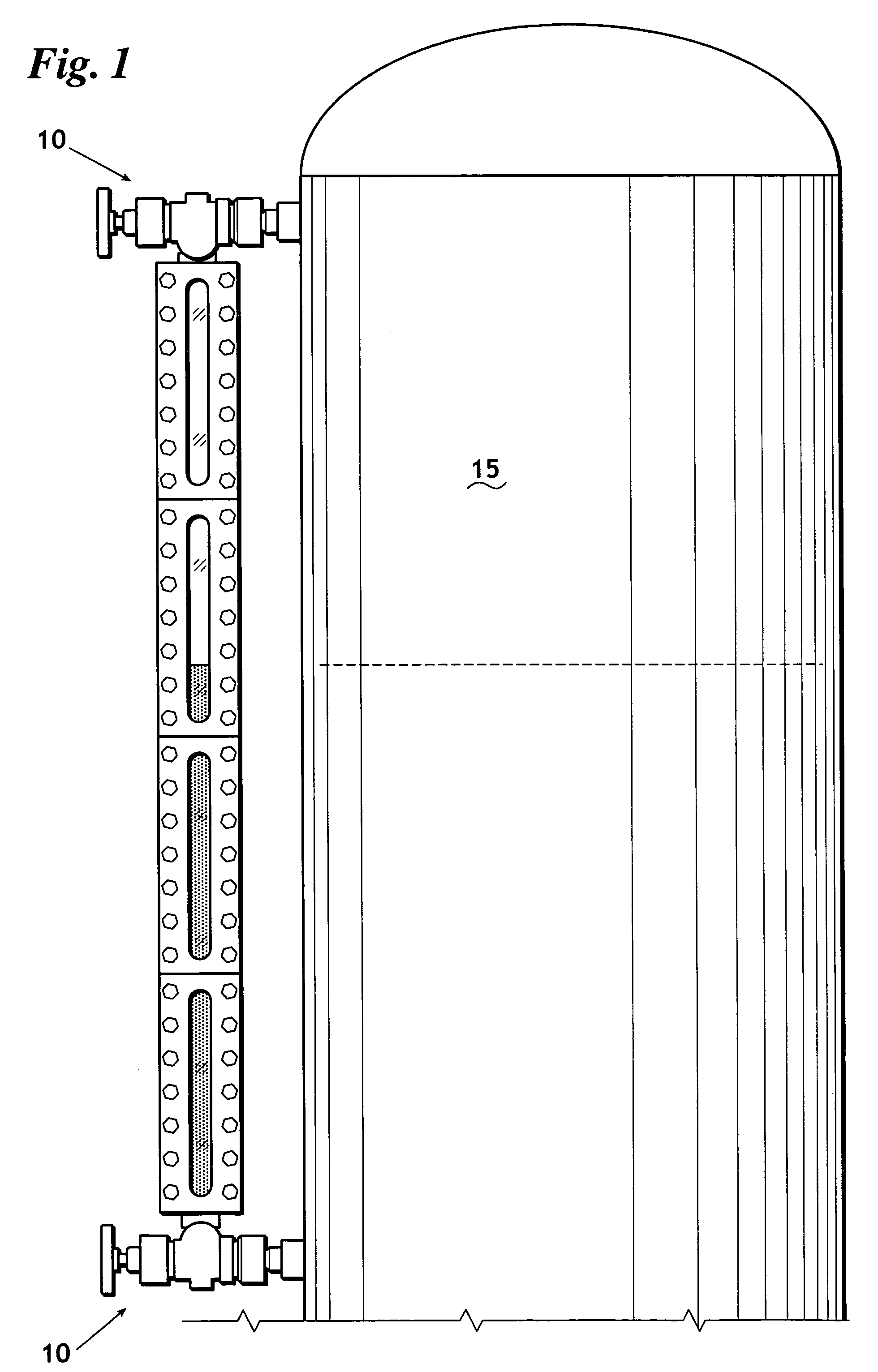
[0035]Referring now to FIGS. 1–5, shown is a valve designated generally 10. Referring in particular to FIGS. 2 and 3, a first embodiment 11 of valve 10 is shown. Valve 11 has a body 12 having a first end 14 and a second end 16. Body 12 comprises valve unit 13. First end 14 has external threads 18 formed thereon. External threads 18 preferably receive a union nut 20 that secures the body 12 to a vessel, e.g. vessel 15 (FIG. 1) by engaging a floating shank 22 (FIG. 3). Second end 16 of body 12 preferably has external threads 24 for receiving a bonnet nut 26.

[0036]Referring now primarily to FIG. 3, body 12 has a passageway 28 formed therein. Passageway 28 extends from first end 14 to second end 16 of body 12. First end 14 of passageway 28 is preferably the valve inlet. Passageway 28 defines a check ball chamber 30 in having a first end 32 and a second end 34. First end 32 of check ball chamber 30 communicates with first end 14 of body 12. Check ball chamber 30 preferably has a tapered ...


PUM


Abstract

A valve, such as a liquid level sight glass gage valve, has a valve unit and a passageway that extends through the valve unit. The passageway has a stem receiving area, a seal receiving area, and a bonnet receiving area that has a non-circular inner perimeter. A packing assembly is provided to isolate the bonnet receiving area from the fluid path. A bonnet is located within the bonnet receiving areas and has a non-circular outside surface for mating relationship with the non-circular inner perimeter of the valve unit. A valve stem is in sealing relationship with the packing assembly and selectively engages a valve seat. The stem threadably engages the bonnet. A bonnet nut is threadably received on the valve unit for securing the bonnet within the valve unit and allowing axial movement of the bonnet against the packing assembly, thereby effecting compression of the packing.

Description

FIELD OF THE INVENTION[0001]The present invention is directed toward a valve. More particularly, but not by way of limitation, the present invention is directed towards an improved valve that resists freeze up due to internal corrosion or fouling of the valve mechanism.BACKGROUND OF THE INVENTION[0002]Sight glass liquid level gages have a vertical window that allows the level of a liquid in a vessel to be determined. Level gages are selectively isolated from vessel contents by valves to enable removal of a level gage for cleaning or repair without dumping the contents of the vessel. Liquid level gage valves are used in pairs, one on each end of a level gage. Typically, liquid level gage valves have a safety ball check that functions to quickly seat and prevent the vessel from emptying in the event of a break of the gage glass. Gage glass breakage will result in a sudden drop in pressure across the gage valve, which seats the safety ball. The valve may then be manually closed and the...

Claims


Application Information

Patent Timeline
IPC IPC(8): F16K41/00
CPCF16K41/02
Inventor WILSON, STEVE B.
Owner INFERNO MFG CORP
Why Eureka
Try Eureka