Conductive polishing article for electrochemical mechanical polishing

a technology of electrochemical mechanical polishing and polishing article, which is applied in the direction of abrasive surface conditioning device, scraping machine, textiles and paper, etc., can solve the problems of general non-interface between the conductive material and the barrier layer, the excess copper material, and the special fabrication problems of copper, etc., to facilitate the flow of material

Inactive Publication Date: 2006-01-31
APPLIED MATERIALS INC
View PDF201 Cites 42 Cited by
  • Summary
  • Abstract
  • Description
  • Claims
  • Application Information

AI Technical Summary

Benefits of technology

[0019]In another aspect, a polishing article is provided for processing a substrate surface, such as a conductive layer deposited on the substrate surface. The polishing article include a body comprising at least a portion of fibers coated with a conductive material, conductive fillers, or combinations thereof, and adapted to polish the substrate. A plurality of perforations and a plurality of grooves may be formed in the polishing article to facilitate flow of material through and around the polishing article.

Problems solved by technology

However, copper has its own special fabrication problems.
However, copper fill of the features usually results in excess copper material, or overburden, on the substrate surface that must be removed to form a copper filled feature in the dielectric material and prepare the substrate surface for subsequent processing.
One challenge that is presented in polishing copper materials is that the interface between the conductive material and the barrier layer is generally non-planar and residual copper material is retained in irregularities formed by the non-planar interface.
Further, the conductive material and the barrier materials are often removed from the substrate surface at different rates, both of which can result in excess conductive material being retained as residues on the substrate surface.
Copper material is removed at different removal rates along the different surface topography of the substrate surface, which makes effective removal of copper material from the substrate surface and final planarity of the substrate surface difficult to achieve.
However, overpolishing of some materials can result in the formation of topographical defects, such as concavities or depressions in features, referred to as dishing, or excessive removal of dielectric material, referred to as erosion.
The topographical defects from dishing and erosion can further lead to non-uniform removal of additional materials, such as barrier layer materials disposed thereunder, and produce a substrate surface having a less than desirable polishing quality.
Another problem with the polishing of copper surfaces arises from the use of low dielectric constant (low k) dielectric materials to form copper damascenes in the substrate surface.
Low k dielectric materials, such as carbon doped silicon oxides, may deform or fracture under conventional polishing pressures (i.e., about 6 psi), called downforce, which can detrimentally affect substrate polish quality and detrimentally affect device formation.
For example, relative rotational movement between the substrate and a polishing pad can induce a shear force along the substrate surface and deform the low k material to form topographical defects, which can detrimentally affect subsequent polishing.
However, the contact ring has been observed to exhibit non-uniform distribution of current over the substrate surface, which results in non-uniform dissolution, especially during overpolishing where a ring of conductive contacts doesn't efficiently remove residues.
However, conventional polishing pads often limit electrolyte flow to the surface of the substrate.
Additionally, the polishing pad may be composed of insulative materials that may interfere with the application of bias to the substrate surface and result in non-uniform or variable dissolution of material from the substrate surface.

Method used


Image

  • Conductive polishing article for electrochemical mechanical polishing
  • Conductive polishing article for electrochemical mechanical polishing
  • Conductive polishing article for electrochemical mechanical polishing

Examples


Embodiment Construction

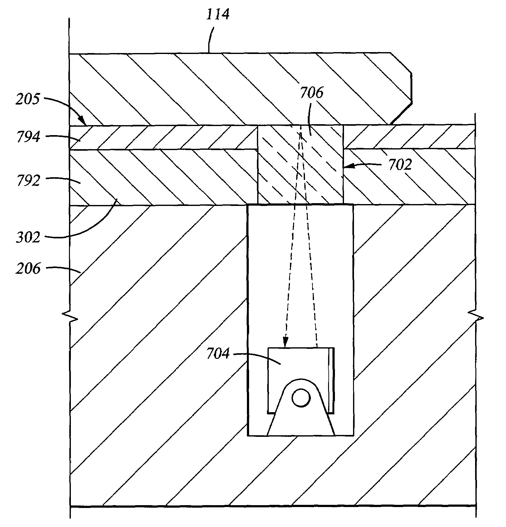
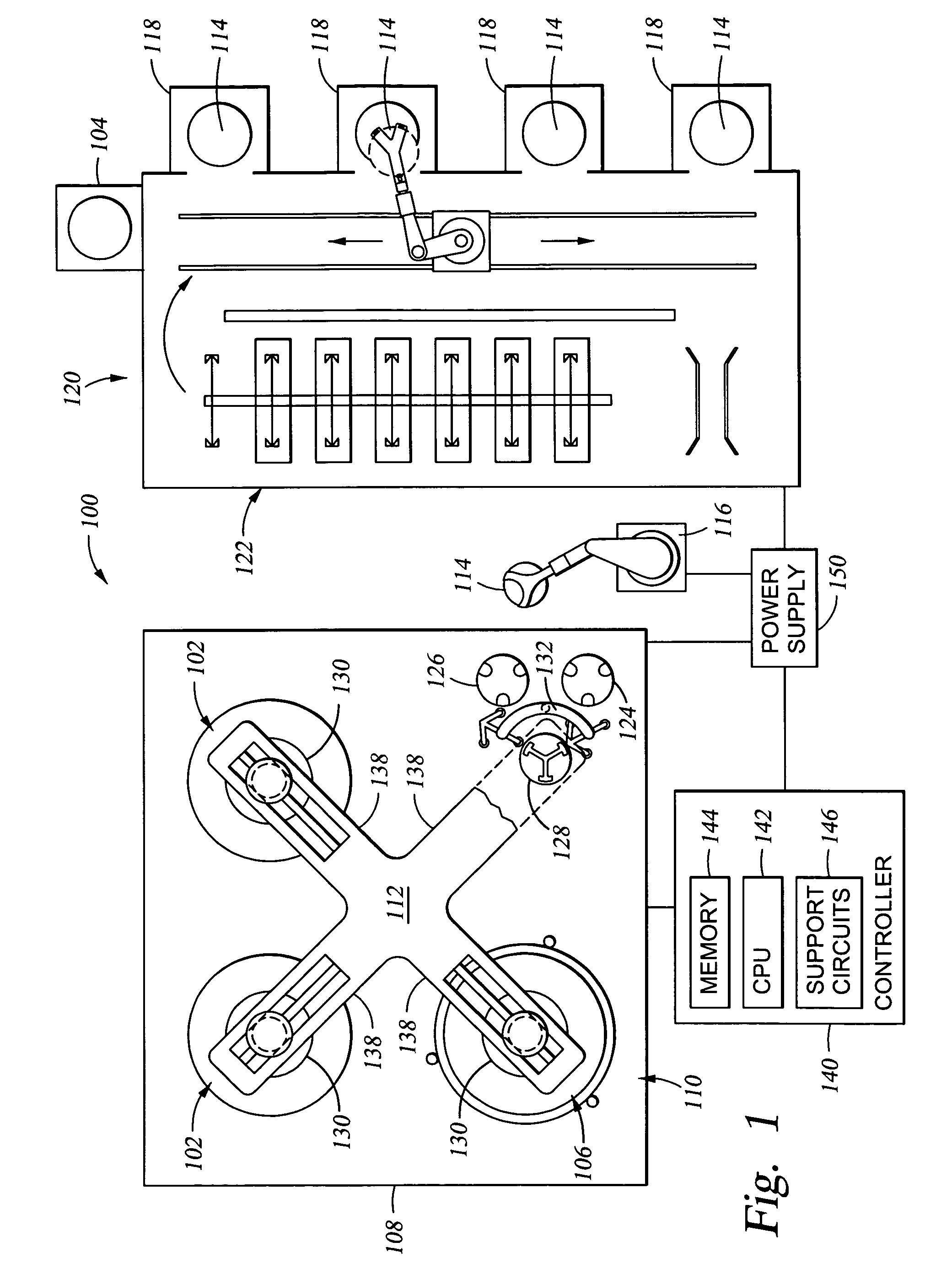
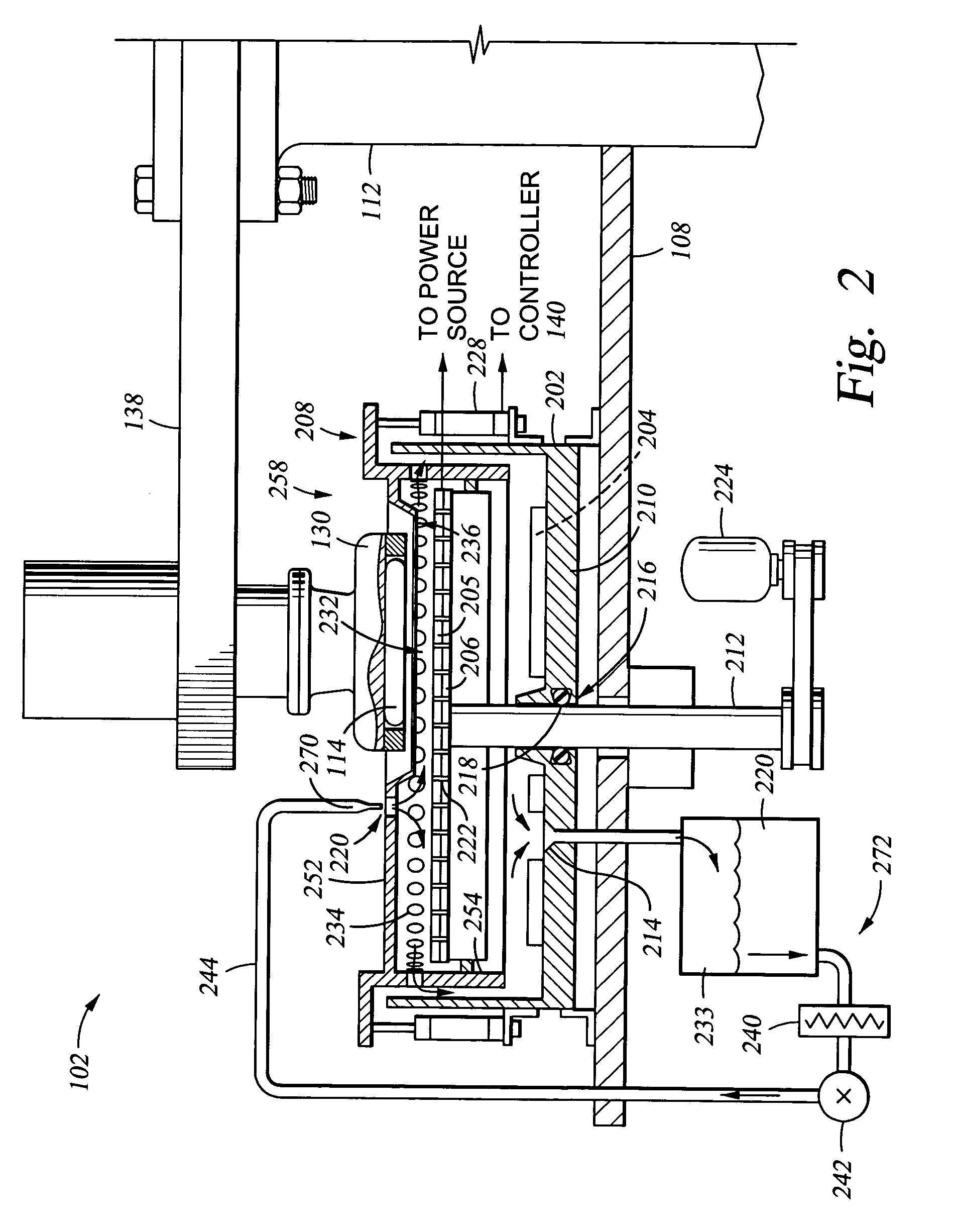
[0056]The words and phrases used herein should be given their ordinary and customary meaning in the art by one skilled in the art unless otherwise further defined. Chemical-mechanical polishing should be broadly construed and includes, but is not limited to, abrading a substrate surface by chemical activity, mechanical activity, or a combination of both chemical and mechanical activity. Electropolishing should be broadly construed and includes, but is not limited to, planarizing a substrate by the application of electrochemical activity, such as by anodic dissolution.

[0057]Electrochemical mechanical polishing (ECMP) should be broadly construed and includes, but is not limited to, planarizing a substrate by the application of electrochemical activity, chemical activity, mechanical activity, or a combination of electrochemical, chemical, and mechanical activity to remove material from a substrate surface.

[0058]Electrochemical mechanical plating process (ECMPP) should be broadly constr...


PUM

PropertyMeasurementUnit
surface roughnessaaaaaaaaaa
dielectric constantsaaaaaaaaaa

Abstract

Embodiments of a polishing article for processing a substrate are provided. In one embodiment, a polishing article for processing a substrate comprises a fabric layer having a conductive layer disposed thereover. The conductive layer has an exposed surface adapted to polish a substrate. The fabric layer may be woven or non-woven. The conductive layer may be comprised of a soft metal and, in one embodiment, the exposed surface may be planar.

Description

CROSS-REFERENCE TO RELATED APPLICATIONS[0001]This application is a continuation-in-part of co-pending U.S. patent application Ser. No. 10 / 140,010, filed May 7, 2002. This application is also a continuation-in-part of co-pending U.S. patent application Ser. No. 10 / 211,626, filed Aug. 2, 2002, which is a continuation-in-part of co-pending U.S. patent application Ser. No. 10 / 033,732, filed Dec. 27, 2001, which is a continuation-in-part of co-pending U.S. patent application Ser. No. 09 / 505,899, filed Feb. 17, 2000. This application is additionally a continuation-in-part of co-pending U.S. patent application Ser. No. 10 / 210,972, filed Aug. 2, 2002, which is also a continuation-in-part of co-pending U.S. patent application Ser. No. 09 / 505,899. This application is further continuation-in-part of co-pending U.S. patent application Ser. No. 10 / 151,538, filed May 16, 2002. All of the above referenced applications are hereby incorporated by reference in their entireties. This application is re...

Claims


Application Information

Patent Timeline
Patent Type & Authority Patents(United States)
IPC IPC(8): B23H3/00B23B5/02B23H5/08B23H5/10B24B37/04B24B53/007B24D13/14H01L21/321
CPCB23H5/08B23H5/10B24B37/046B24B37/14B24B37/16H01L21/32125B24B37/22B24B37/24B24B37/26B24B53/017B82Y30/00B24B37/205Y10T428/249924
Inventor HU, YONGQIWANG, YANDUBOUST, ALAINLIU, FENG Q.MANENS, ANTOINE P.NEO, SIEW S.TSAI, STAN D.CHEN, LIANG-YUHBUTTERFIELD, PAUL D.TIAN, YUAN A.KO, SEN-HOU
Owner APPLIED MATERIALS INC
Why Eureka
Try Eureka