Method and apparatus of obtaining balanced phase shift

a phase shift and phase shift technology, applied in waveguides, delay lines, resonators, etc., can solve the problems of generating radiation nulls, reducing the cost of beam forming in this manner, and increasing the cost of the antenna array system

Inactive Publication Date: 2006-01-31
HOW HOTON
View PDF1 Cites 13 Cited by
  • Summary
  • Abstract
  • Description
  • Claims
  • Application Information

AI Technical Summary

Problems solved by technology

Also, there is a need to create radiation nulls along certain spatial directions for an antenna transmitter / receiver to warrant secure and covert communications.
However, beam forming in this manner is costly; depending on the speed, frequency, and angle of steering, each phase-shifting element can cost as much as $10 0˜1,000, and in a system containing 10,000 elements, the cost of the antenna array system becomes formidable.
However, steering in this manner is slow, suffering from potential mechanical breakdowns.
As such, it is unlikely to apply a mechanically rotating radar in a body moving at high speed.
However, the current collision avoidance radars perform only the basic functions for target detection; these radars are not able to recognize a target, and hence they do not have the intelligence to handle targets of different kinds.
The prior art is not able to accomplish this purpose.
However, to obtain a large angle in phase shift a long line is needed, which translates into high cost and large volume.
Also, insertion loss can be a serious problem if the phase shifter demands a long transmission line to operate.
Otherwise, significant return loss will result, if the electric property of the transmission line has been changed appreciably due to the resultant change in line impedance.
Even worse, in applications for a large phased array a large number of phase shifters is required, and there are problems such as how to integrate the phase shifters with the array system providing compatibility and uniformity with economy and size fit.
The prior-art circuit is unbalanced and phase shifts thus obtained shows variations in insertion loss.
By applying a pair of counter reacting magnetic fields onto the two sides of the resonator at symmetry balanced phase shift results, showing insignificant variation in insertion loss.
Balanced phase shifts result if a pair of secondary axial fields is applied counter-balancing each other, but showing insignificant variation in insertion loss.
By applying counter-reacting voltages onto the ferroelectric materials balanced phase shifts result, showing insignificant variation in insertion loss.
By applying counter-reacting currents and voltages onto the respective ferrite and ferroelectric materials balanced phase shifts result, showing insignificant variation in insertion loss.
By applying counter-reacting voltages onto the varactor diodes balanced phase shifts result, showing insignificant variation in insertion loss.

Method used


Image

  • Method and apparatus of obtaining balanced phase shift
  • Method and apparatus of obtaining balanced phase shift
  • Method and apparatus of obtaining balanced phase shift

Examples


Embodiment Construction

Prior-Art Explanation:—FIG. 1

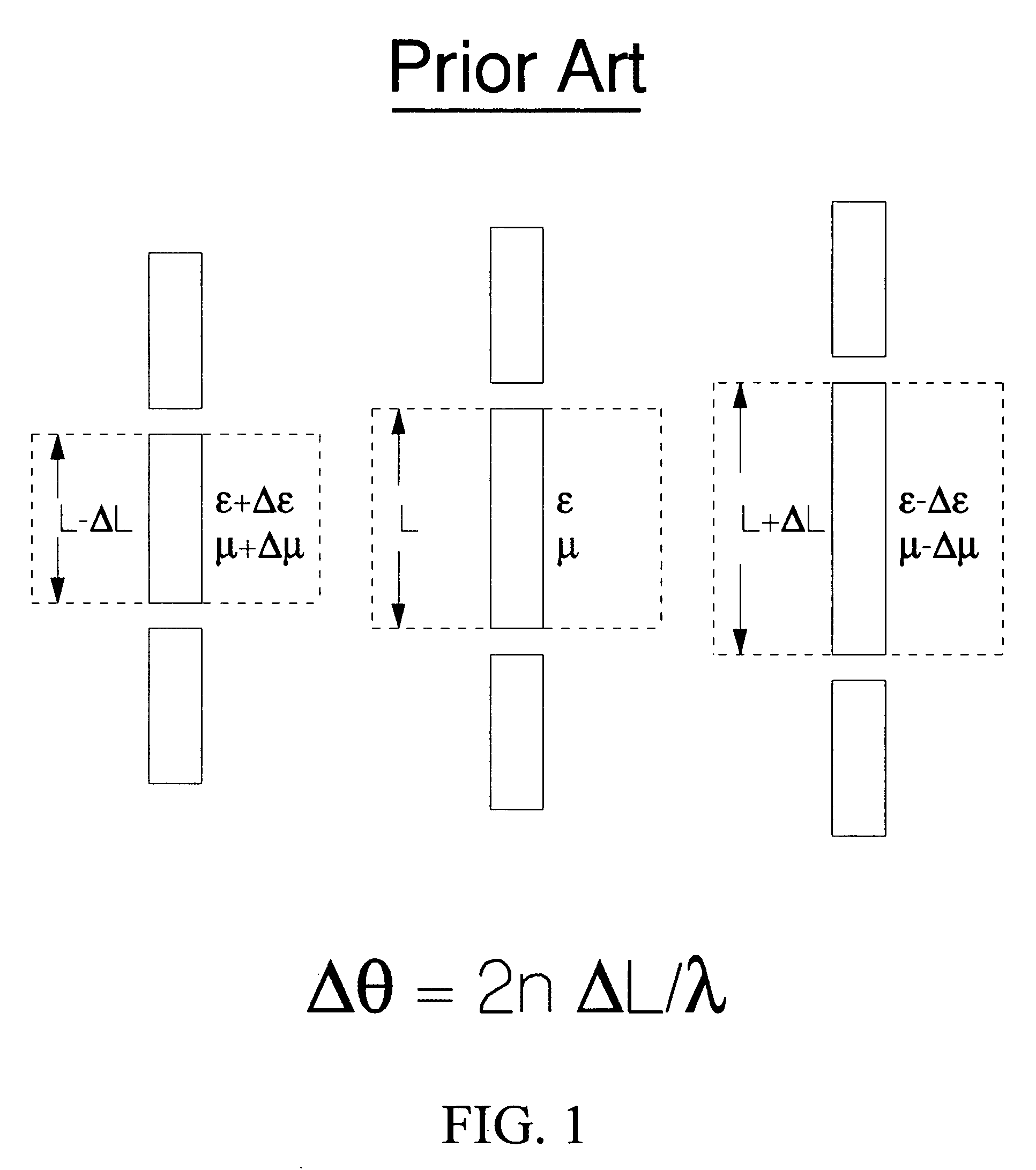
[0025]FIG. 1 shows the prior art that phase shifts are derived from a linear resonator supporting reciprocal wave propagation. As shown by the middle circuit of FIG. 1 a linear resonator of length L is characterized by the two electronic parameters ε and μ, denoting the capacitance per unit length and inductance per unit length, respectively. If these two parameters are changed via, say, electronic means, the electrical length of the linear resonator will change accordingly, resulting in a shorter or a longer resonance length, corresponding to the increase of ε and μ to ε+Δε and / or μ+Δμ, shown at left of FIG. 1, and the decrease of ε and μ to ε−Δε and / or μ−Δμ, shown at right of FIG. 1, respectively. The derived angle in phase shift is

Δθ=2n ΔL / λ,  (1)

where ΔL denotes the change in electrical length of the resonator, λ is the wavelength, and n is the order of resonance, for example n=0.5 for half-wave resonance, and n=1 for full-wall resonance, etc. Howeve...


PUM


Abstract

Disclosed is a method and an apparatus enabling operation of balanced phase shifts providing uniformity that the insertion loss do not show variation with the derived angles in phase shift. The invention incorporates a resonator supporting nonreciprocal wave propagation. The resonator is divided in two equal parts showing symmetry so that the change in electronic parameters from one part of the resonator counter balances the other part, thereby causing no change to the resonance condition. Amplifiers are thus not needed by the phase-shift operation. Electronically active materials, such as ferrites, ferroelectrics, and / or varactors, are utilized, and the phase shifter device can be fabricated assuming a variety of transmission-line geometries, such as microstrips, striplines, waveguides, coax lines, parallel wires, coplanar waveguides, image lines, fin lines, and slot lines, providing versatility and convenience in applications.

Description

FEDERALLY SPONSORED RESEARCH[0001](Not Applicable)SEQUENCE LISTING OR PROGRAM[0002](Not Applicable)BACKGROUND[0003]1. Field of Invention[0004]This invention is directed to a method and an apparatus to obtain balanced phase shift from a resonator supporting nonreciprocal wave propagation. As such, uniform phase shift results whose amplitude shows insignificant dependence on the derived angle in phase shift thereby eliminating the need for an amplifier.[0005]2. Prior Art[0006]Microwave and millimeter-wave (MMW) devices and systems are becoming increasingly important today for both defense and commercial applications. For example, in the collision avoidance industries, low-profile antennas are needed providing electronically steerable radiations to detect and identify obstacles and protrusions in front of a moving vehicle. Upon navigation the receiver antennas need to follow and track the motion of GPS (Global Positioning Systems) satellites so as to continuously monitor and update the...

Claims


Application Information

Patent Timeline
Patent Type & Authority Patents(United States)
IPC IPC(8): H01P1/19
CPCH01P1/32H01P1/19
Inventor HOW, HOTON
Owner HOW HOTON
Why Eureka
Try Eureka