Low profile polarization-diverse herringbone phased array

a phased array, low-profile technology, applied in the field of antennas, can solve the problems of affecting the size and weight of low-frequency antenna systems, significant secondary inefficiencies in power and heat generation, and the limitations of radiators in broadband array applications

Active Publication Date: 2006-01-31
HARRIS CORP
View PDF10 Cites 23 Cited by
  • Summary
  • Abstract
  • Description
  • Claims
  • Application Information

AI Technical Summary

Benefits of technology

[0010]The multiple microstrips of the present invention are disposed approximately one-quarter wavelength above a ground plane. The planar substrate of the present invention is mounted on a composite substrate having a permittivity and permeability matched at a mid-band frequency of operation to achieve an impedance of approximately 377 ohms. The composite substrate is approximately 1/16 of a wavelength in thickness. The composite substrate ...

Problems solved by technology

Consequently, size and weight of low-frequency antenna systems are of concern.
To circumvent these limitations, shortened and inefficient antennas have been developed, which produced undesirable radiation performance and caused significant secondary inefficiencies in power and heat generation.
These radiators have limitations in broadband array applications, due to their element size tha...

Method used


Image

  • Low profile polarization-diverse herringbone phased array
  • Low profile polarization-diverse herringbone phased array
  • Low profile polarization-diverse herringbone phased array

Examples


Embodiment Construction

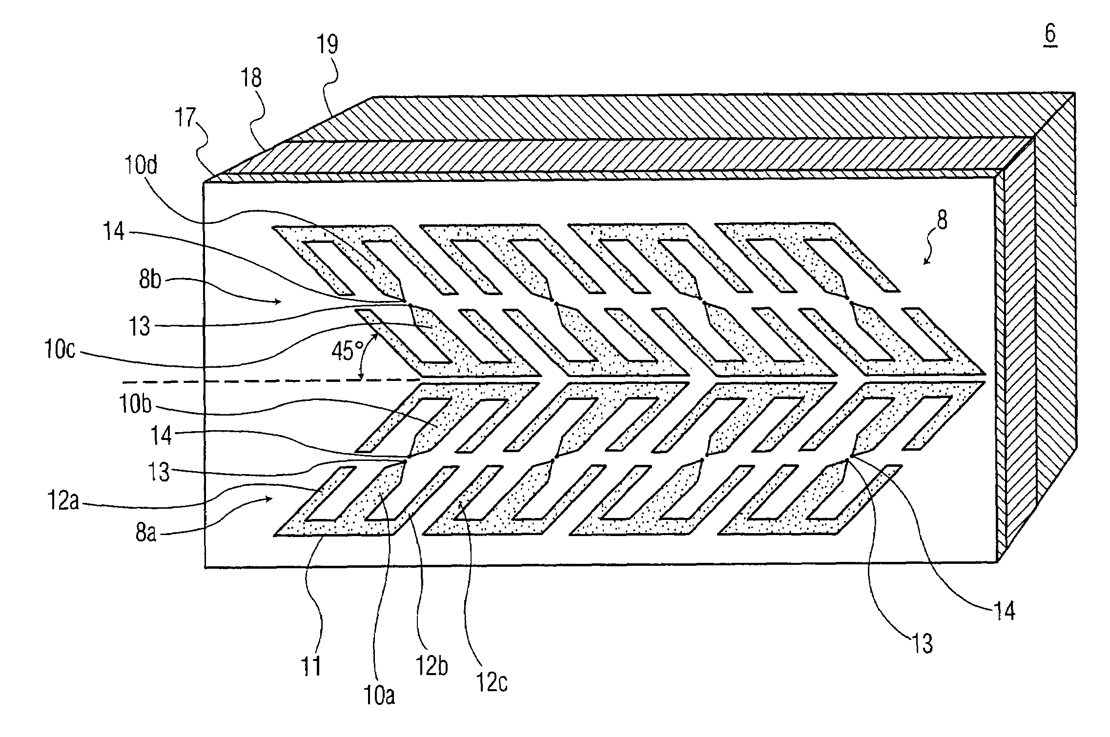
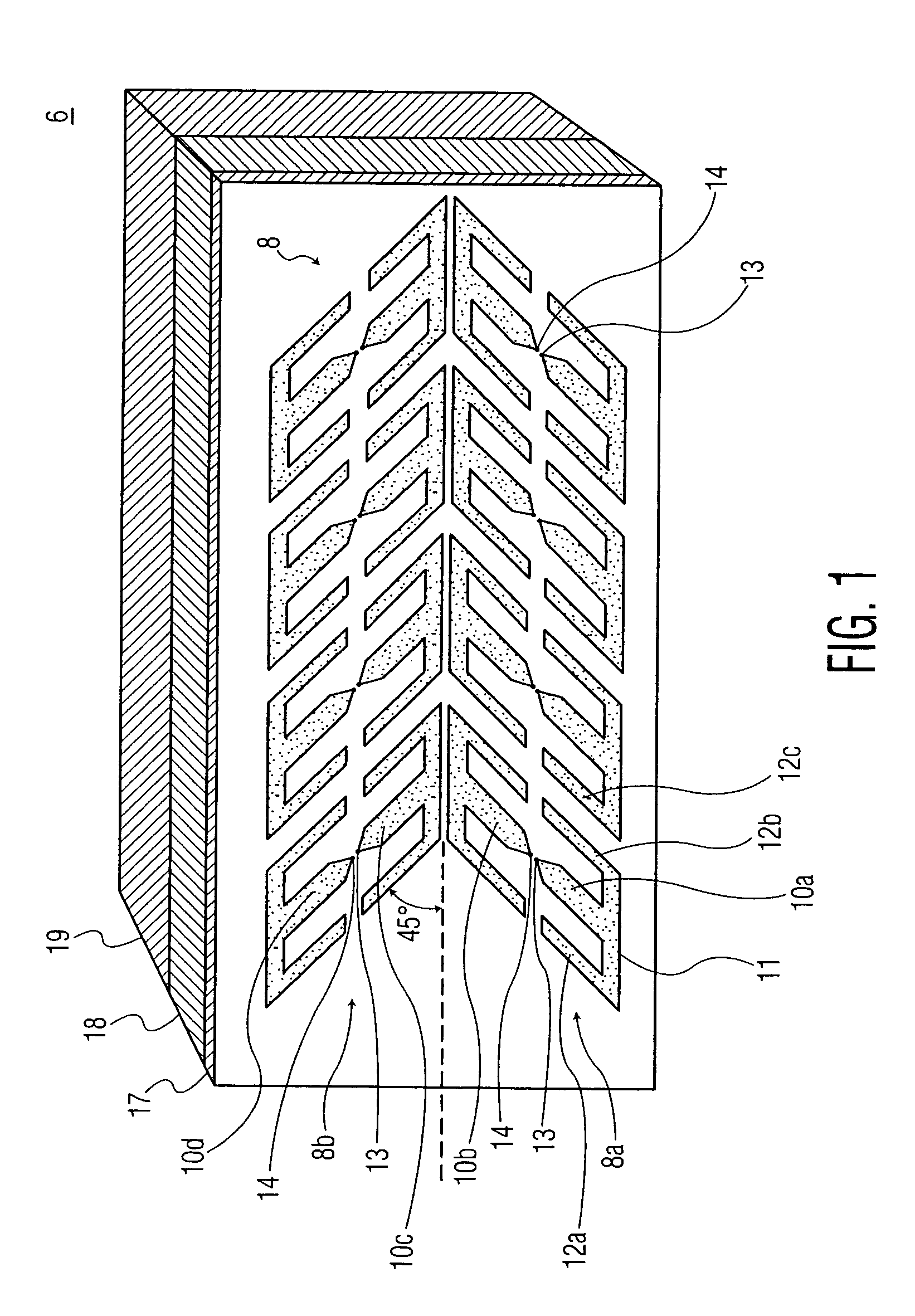
[0021]Referring to FIG. 1, there is shown a partial perspective view of a phased array antenna, in accordance with an embodiment of the invention. As shown, phased array antenna 6 includes multiple radiating elements 8, which are arranged as orthogonal pairs in a herringbone pattern. Each orthogonal pair of radiating elements includes multiple microstrips that are formed conformally on a thin substrate. The substrate is generally designated as 17. The orthogonal pairs of radiating elements 8 are positioned 45 degrees relative to a scan axis of the phased array antenna.

[0022]Each radiating element 8 includes a dipole formed from a pair of dipole microstrips, generally designated as 10a and 10b. Each dipole microstrip of the pair of dipole microstrips extends from launch point 13 or launch point 14. In this manner, each dipole is excited or fed in a balanced mode, at feed points or launch points 13 and 14. For discussion purpose only, FIG. 1 shows 8 radiating elements or 8 dipoles, ea...


PUM


Abstract

A phased array antenna includes a plurality of radiating elements arranged as orthogonal pairs in a herringbone pattern. Each radiating element includes multiple microstrips disposed conformally on a planar substrate. Each radiating element includes a dipole formed as a pair of dipole microstrips extending from a pair of launch points. Each dipole microstrip extends between one launch point of the pair of launch points and a top loading microstrip, which provides a capacitive load to the dipole. The top loading microstrip extends between parallel microstrips, which provide an additional capacitive load to the dipole.

Description

FIELD OF THE INVENTION[0001]The present invention relates, in general, to an antenna and, more specifically, to a phased array antenna including multiple radiating elements arranged in a herringbone pattern. The phased array antenna operates over multi-octave bandwidths, subtends a wide field-of-view, and is capable of producing any desired polarization in space.BACKGROUND OF THE INVENTION[0002]Modern phased array systems are required to operate over wide frequency bandwidths with a single radiating aperture. In such broad band environments, processing functions that have previously been performed by individual antennas, need now to be performed by a single phased array.[0003]A critical parameter of many RF signals is their polarization, requiring an array to respond to any linear, circular or elliptical polarization. This in the art is known as polarization diversity or polarization agility. Antenna polarization agility may be achieved with orthogonally disposed pairs of radiating ...

Claims


Application Information

Patent Timeline
IPC IPC(8): H01Q9/28H01Q1/38
CPCH01Q9/065H01Q21/24H01Q21/062
Inventor MOHUCHY, WOLODYMYR
Owner HARRIS CORP
Why Eureka
Try Eureka