
High speed signal enhancement using pixons

a high-speed, signal-enhancing technology, applied in image enhancement, image analysis, instruments, etc., can solve the problems of lack of clarity, low contrast and blur, negatively affecting etc., to improve image sharpness and detail, improve image quality, and reduce noise

Active Publication Date: 2006-01-31
PIXON
View PDF25 Cites 89 Cited by
  • Summary
  • Abstract
  • Description
  • Claims
  • Application Information

AI Technical Summary

Benefits of technology

[0010]It is an advantage of the present invention to provide a method for enhancement and reconstruction of images in substantially real time.
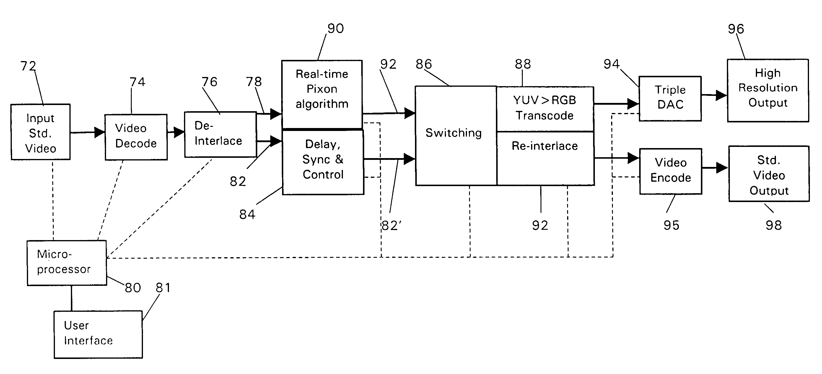
[0011]It is another advantage of the present invention to provide a system for real-time image enhancement for use with color video or other high speed output devices.
[0012]In an exemplary embodiment, input data comprising a video signal is processed using a combination of conventional image processing methods to deblur, or sharpen, the image and convolution with Pixon™ kernels for smoothing. The image processing and smoothing operations may be performed as four steps comprising generating an estimated image model based on the input data, where the input data comprises a plurality of image grid points, calculating a Pixon™ map to determine the degree of smoothing to be applied in each location within the image, deconvolving the input data, and smoothing the data with a spatially-variable smoothing kernel function according to the Pixon™ map to generate an output image. The order of the last two steps can be varied. For example, the (deblurred) image produced by the image processing operation can be smoothed according to the Pixon™ map. Alternatively, the smoothed image produced by using the Pixon™ map can be deblurred by the image processing operation. In the preferred embodiment, the image processing is by convolution with an approximate inverse point response function (PRF). Where the deblurring operation is performed prior to smoothing, any known image processing method, including direct or indirect methods, can be used. Minimally, the input data corresponds to at least one frame of the video signal. The step of generating an initial estimate of the image model is accomplished by coadding the input data. For a single data frame, the coadded data is the data; i.e., the input image is the image model. Generally, however, multiple data frames are input, with the multiple frames being coadded to provide the data to be processed.
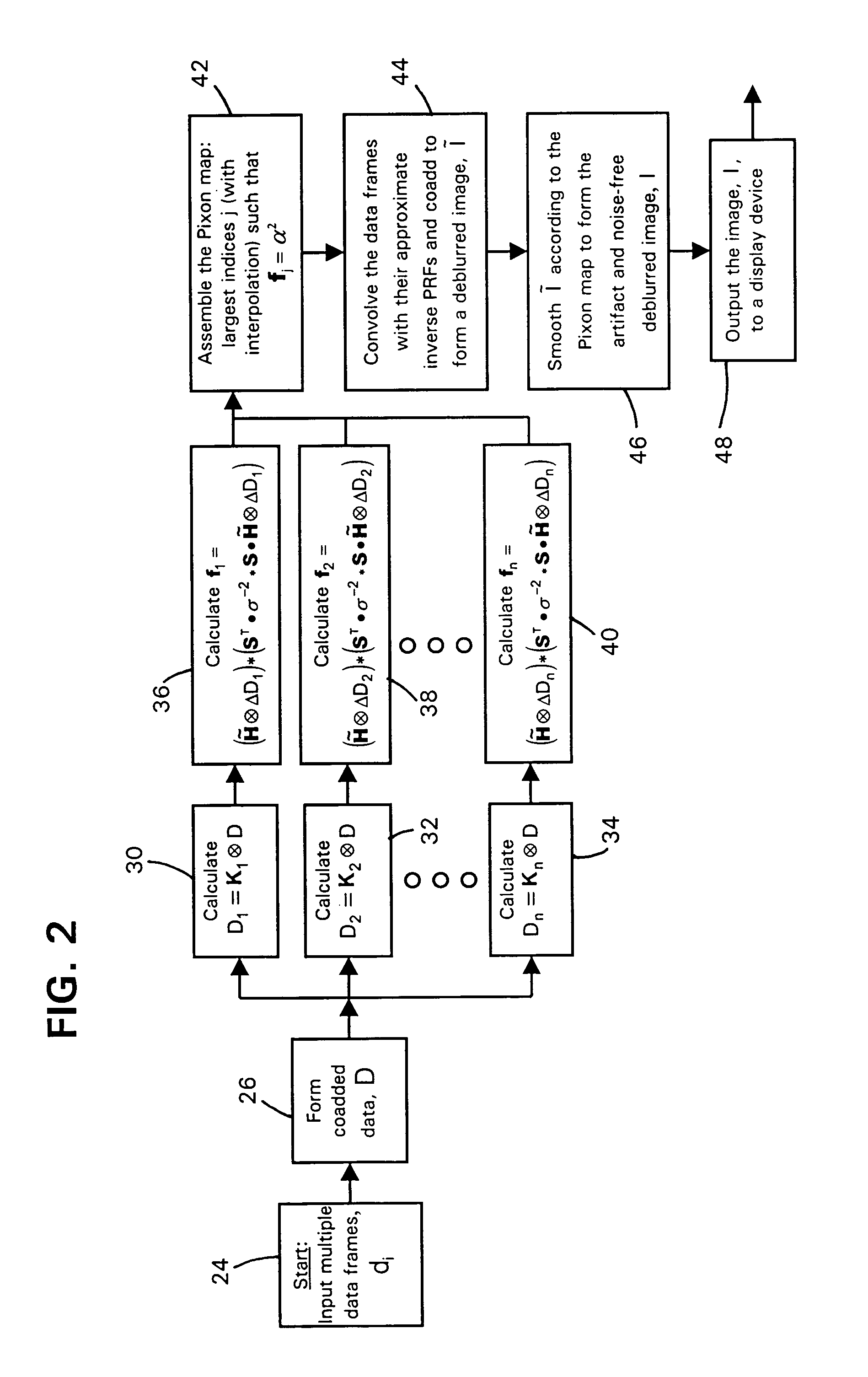
[0013]Calculation of the Pixon™ map is achieved by selecting the broadest Pixon™ elements required to fit the data. Using a plurality of different size Pixon™ kernels, the image model is simultaneously convolved with each different Pixon™ kernel and the PRF. The resulting noise free data models are compared to the input data and the smoothed data obtained using the broadest Pixon™ kernel that fits the input data within a predetermined criteria are selected to form the Pixon™ map. The Pixon™ map is assembled using the indices of the broadest kernels that meet the acceptance criteria for local quality of fit. Smoothed data is then formed according to the Pixon™ map. The smoothed data is deconvolved (deblurred) and output to a video display or other appropriate device, providing a clearer image with less noise. Alternatively, the deblurred image formed by directly deconvolving the input data is smoothed according to the Pixon™ map, and the resulting image is output to the video display device.
[0014]In one embodiment, input data in the form of a video signal comprising a data frame with a plurality of pixel values within a pixel array is input into a system processor that runs software to perform operations for deblurring and smoothing. Deblurring is performed using methods known in the art, for example, Wiener filter Fourier deconvolution (“Wiener deconvolution”) or other fast Fourier transform (“FFT”) methods, such as convolution with an inverse PRF, or inverse PRF kernel convolution by direct summation. Indirect methods such as non-negative least squares modeling and other maximum likelihood (“ML”) methods can also be used. The functional form of the deconvolution kernels is preferably selectable by a system user to optimize deblurring and minimize noise. Smoothing of the data comprises small kernel convolutions with Pixon™ elements. The choice of Pixon™ kernel used for smoothing at each location, e.g., kernel size and shape, is made by testing the change in data brought about by smoothing with a plurality of different kernels K1 through Kn. In the preferred embodiment, the fit criterion for a given kernel is determined by performing a Taylor series expansion on the change in χ2, i.e., Δχ2. To increase the speed of the kernel selection process for smoothing, the input data is processed in parallel using each of the different possible kernels. A Pixon™ map is assembled using the indices of the broadest kernels that meet the criteria for acceptance, which is a function of the standard deviation of the noise. Once the smoothed data are assembled, they are deconvolved to form the reconstructed image. The reconstructed image is then output to a video display device.
[0015]In another embodiment, the input data consisting of a single input image, single data frame, of a video signal is smoothed in parallel using small kernel convolution with a plurality of Pixon™ kernels, each Pixon™ kernel having a different size. By selecting the broadest Pixon™ kernel that meets the fit criterion for each portion of the data, a Pixon™ map is generated. The smoothed data is convolved with an inverse PRF to form a reconstructed image which is output to a video display device.

Problems solved by technology

At this point, image reconstruction is required to remove the instrumental signatures Applications of image enhancement, and the sources of noise and other factors that can negatively impact data extraction efficiency cover a wide range including astronomical observation and planetary exploration, where sources can be faint and atmospheric interference introduce noise and distortion, military and security surveillance, where light can be low and rapid movement of targets result in low contrast and blur, medical imaging, which often suffers from lack of clarity, and video images, where transmission and instrument limitations, and the need for real time response, can negatively impact image sharpness and detail.
The direct methods have the advantage of speed, but they tend to amplify noise, particularly at high spatial frequencies.
The indirect methods supposedly exclude the noise, however, the requirement of imposing a model can be a disadvantage.
Existing indirect methods of image enhancement such as chi-squared fitting and maximum entropy often result in poor quality images, introduce artifacts, and operate at speeds that are too slow for video.
The increased reliance on night-vision and heat-sensing video will only increase the demand for image enhancing devices.
Furthermore, even the more sophisticated medical imaging devices, e.g., nuclear imaging methods, often suffer from noise and lack of contrast which can make diagnosis difficult, such that image enhancement is needed to optimize the imaging system's capabilities.
In other portions of the image, the density of pixels may be too sparse to adequately represent the image.
While such an iterative process is highly effective for enhancement and reconstruction of still images, video enhancement requires real-time or nearly real-time response, making methods with a large number of iterations impractical.

Method used


Image

  • High speed signal enhancement using pixons
  • High speed signal enhancement using pixons
  • High speed signal enhancement using pixons

Examples


Embodiment Construction

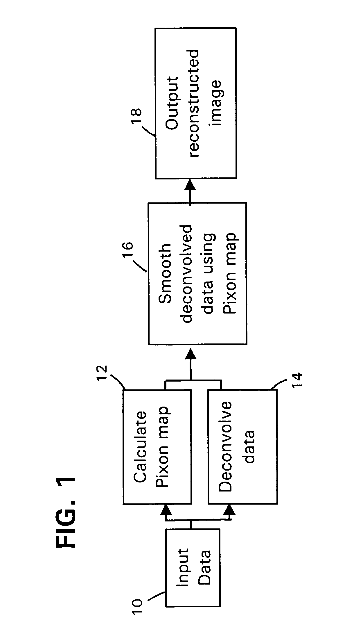
[0025]As shown in FIG. 1, input data 10 consist of points of a digitized image, i.e., an image comprising a plurality of pixels, where each pixel represents an image data point. The input data 10 are processed by a combination of one or more conventional image processing techniques to form an image model that is smoothed by a plurality of different Pixon™ kernels and the PRF (point response function) to construct a Pixon™ map in step 12. Pixon™ elements, or kernels, are fundamental and indivisible units of information typically made up of a plurality of pixels. The actual Pixon™ elements selected during the reconstruction process represent the smallest number of such units required to fit the data and represent the minimum number of parameters necessary to specify the image. The Pixon™ kernels can have arbitrary properties, e.g., shape, size, and / or position, as needed to best fit the data. The exact shapes of the Pixon™ smoothing kernels are not critical as long as they are central...


PUM


Abstract

Input data comprising a video signal is processed using a combination of a known image processing method to deblur, or sharpen, the image and convolution with Pixon™ kernels for smoothing. The smoothing process utilizes a plurality of different size Pixon™ kernels which operate in parallel so that the input data are convolved with each different Pixon™ kernel simultaneously. The smoothed image is convolved with the point response function (PRF) to form data models that are compared against the input data, then the broadest Pixon™ kernel that fits the input data within a predetermined criterion are selected to form a Pixon™ map. The data are smoothed and assembled according to the Pixon™ map, then are deconvolved and output to a video display or other appropriate device, providing a clearer image with less noise.

Description

RELATED APPLICATIONS[0001]This application is related to application Ser. No. 09 / 333,172, filed Jun. 14, 1999, now issued as U.S. Pat. No. 6,353,688, which is a continuation-in-part of application Ser. No. 08 / 073,929, filed Jun. 8, 1993, now issued as U.S. Pat. No. 5,912,993. The disclosures of both applications are incorporated herein by reference.FIELD OF THE INVENTION[0002]The present invention relates generally to a method for signal reconstruction and enhancement and more specifically to a method for real time enhancement of images.BACKGROUND OF THE INVENTION[0003]Optimal extraction of data contained within an electromagnetic signal requires the removal of defects such as noise and instrument limitations. A key area in which optimized extraction and reconstruction of data is sought is the field of image enhancement. Even when the instruments can be made essentially noise-free, instrumental signatures related to finite spatial, spectral, or temporal resolution remain. At this po...

Claims


Application Information

Patent Timeline
Patent Type & Authority Patents(United States)
IPC IPC(8): G06K9/40G06K9/56
CPCG06T5/20G06T5/003G06T5/002G06T2207/10016G06T5/73G06T5/70
Inventor YAHIL, AMOSPUETTER, RICHARD
Owner PIXON
Learn More