Ultra low Nox emissions combustion system for gas turbine engines

a combustion system and gas turbine technology, applied in the combustion process, engine ignition, lighting and heating apparatus, etc., can solve the problems of severe constraints, combustor operation close to blowout limit, and rapid decrease of flame stability

Inactive Publication Date: 2006-02-07
PRATT & WHITNEY CANADA CORP
View PDF29 Cites 37 Cited by
  • Summary
  • Abstract
  • Description
  • Claims
  • Application Information

AI Technical Summary

Problems solved by technology

However, flame stability decreases rapidly under the lean combustion conditions and the combustor may be operating close to its blow-out limit.
In addition, severe constraints are imposed on the homogeneity of the fuel / air mixture since leaner than average pockets of mixture may lead to stability problems and richer than average pockets will lead to unacceptably high NOx emissions.
Nevertheless, major challenges have prevented the implementation of catalytic combustors in a gas turbine engine.
Other major problems in catalyst operation include ignition, engine start-up and catalyst warm up which cannot be performed with the catalyst.
Generally, this compromises the catalyst and engine performance under part load conditions, thereby resulting in emissions leading to very high NOx and CO levels.
The catalyst durability is affected by engine transient operation since catalyst operation is a delicate balancing act between catalyst ignition (blow-out) and catalyst burn-out.
In this sense, turn-down of the catalyst system becomes a serious operability and durability issue.
In addition, hot streaks from the pre-burner are very likely to damage catalyst hardware directly or act as sources of auto-ignition within the fuel / air mixing duct upstream of the catalyst, and impose a substantial risk to catalyst and engine operation.
A pre-burner also substantially increases the combustor pressure drop by an additional 1.5% to 2.5%, which directly affects engine specific fuel consumption.
Because the fuel air mixture in the catalytic reactor bed is lean, the combustion reaction temperature is too low to produce thermal NOx.

Method used


Image

  • Ultra low Nox emissions combustion system for gas turbine engines
  • Ultra low Nox emissions combustion system for gas turbine engines
  • Ultra low Nox emissions combustion system for gas turbine engines

Examples


Embodiment Construction

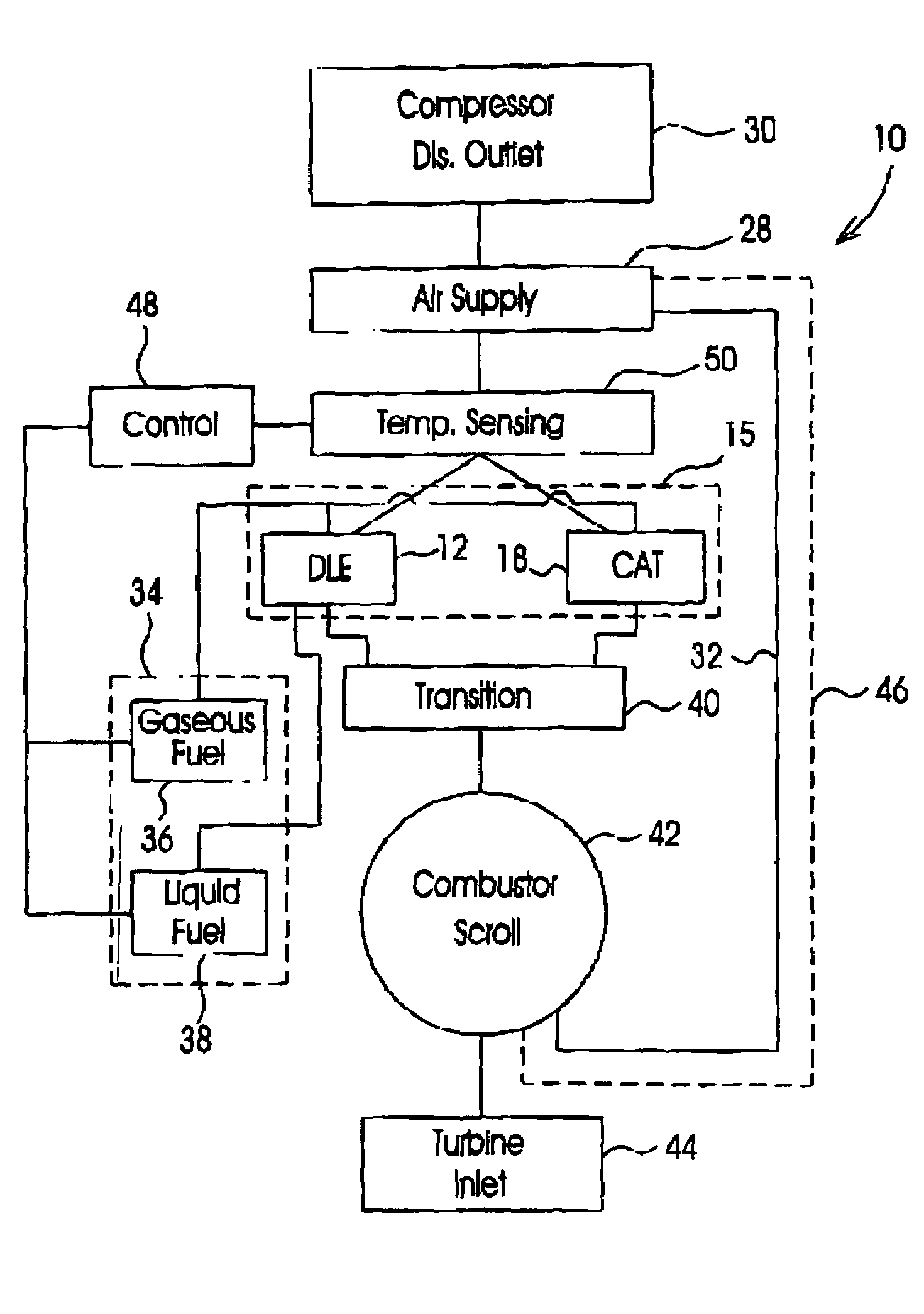
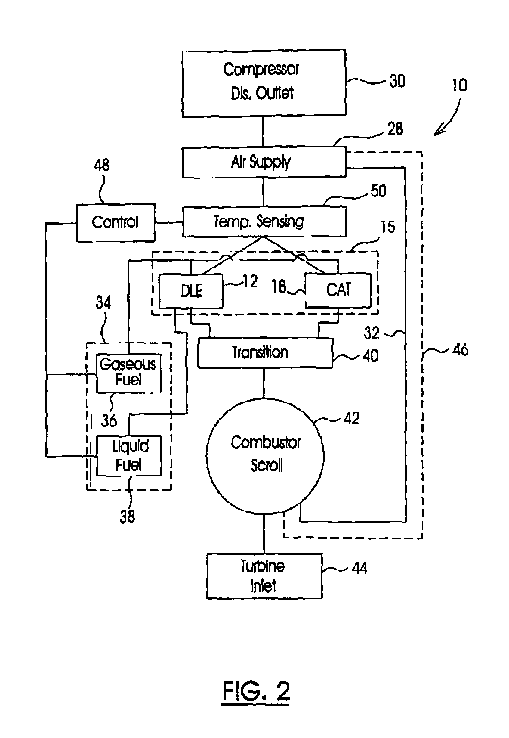
[0018]Referring to the drawings, particularly to FIGS. 2 and 3, the invention describes a combustion system, generally indicated at numeral 10, that permits the operation of a gas turbine engine at highest engine efficiency while minimizing the emissions of nitrogen oxide (NOx) and carbon monoxide (CO) from the engine. The combustion system 10 includes a Dry-low-emissions (DLE) combustion sub-system 12 which is generally formed with a fuel / air mixer 14 to provide a lean-premixed fuel / air mixture to the burner 16 to generate combustion products, generally hot gas. The DLE combustion sub-system 12 operates on liquid and gaseous hydrocarbon fuel. The DLE combustion sub-system 12 is conventional, well known in the art and will not be further described. A separate Catalyst (CAT) combustion sub-system 10 is included in the combustion system 10 which operates separately from the DLE combustion sub-system 12.

[0019]The CAT combustion sub-system 18 includes a fuel / air mixer 20 to provide a le...


PUM


Abstract

A combustion system for a gas turbine engine includes a Catalyst (CAT) combustion sub-system for generating combustion products under a lean premixed fuel / air condition in the presence of a Catalyst and a Dry-Low-Emissions (DLE) combustion sub-system, for generating combustion products under a lean premixed fuel / air condition. Gaseous and liquid fuels are used for the DLE combustion sub-system while only gaseous fuel is used for the CAT combustion system. The engine operates at start-up and under low load conditions with the DLE combustion system and switches over the combustion process to the CAT combustion sub-system under high load conditions. Thus the combustion system according to the invention combines the advantages of DLE and CAT combustion processes so that the gas turbine engine operates over an entire operating range thereof at high engine efficiency while minimizing omissions of nitrogen oxides and carbon monoxide from the engine.

Description

CROSS-REFERENCED TO RELATED APPLICATIONS[0001]This application is a continuation of U.S. patent application Ser. No. 10 / 349,243 filed Jan. 23, 2003 now U.S. Pat. No. 6,629,414, and was allowed on Apr. 16, 2003.FIELD OF THE INVENTION[0002]The present invention relates to gas turbine engines, and more particularly, to an ultra low NOx emissions combustion system for gas turbine engines.BACKGROUND OF THE INVENTION[0003]Low NOx emissions from a gas turbine engine, of below 10 volume parts per million (ppmv), are becoming important criteria in the selection of gas turbine engines for power plant applications. Some installations in non-attainment area in the United States are demanding even lower NOx emissions of less than 5 ppmv. The challenging NOx emission requirements must be achieved without compromising the more conventional constraints on gas turbine engines, of durability, low operating costs and high efficiency.[0004]The main factor governing nitrogen oxide formation is temperatu...

Claims


Application Information

Patent Timeline
Patent Type & Authority Patents(United States)
IPC IPC(8): F23R3/40F23C13/02F23R3/36
CPCF23C13/02F23R3/40F23R3/36F23N2037/10F23N2037/12F23N2237/10F23N2237/12
Inventor FISCHER, BERNHARD
Owner PRATT & WHITNEY CANADA CORP
Why Eureka
Try Eureka