Beveled cutter

Inactive Publication Date: 2006-02-07
FAST FUSION
View PDF4 Cites 22 Cited by
  • Summary
  • Abstract
  • Description
  • Claims
  • Application Information

AI Technical Summary

Benefits of technology

[0015]The present invention overcomes the disadvantages and limitations of the prior art by providing a simple method for eliminating the effects of the lips of a butt welded fusion joint. Prior to welding and during the facing operation normally performed as part of the welding process, a profile is cut into the inner diameter of the weld. When the weld is performed, the lips do not protrude into the inner diameter of the pipe. Alternatively, the profile may be designed so as to minimize the external protrusion of the lips.
[0016]The present invention may therefore comprise a method for joining a first plastic pipe to a second plastic pipe with at least a partially recessed internal bead comprising: placing the first plastic pipe in a holder; cutting the first plastic pipe substantially perpendicular to the axis of the first pipe with a profile that reduces the wall thickness of the first pipe with an undercut region on the internal side of the first pipe; cutting the second plastic pipe substantially perpendicular to the axis of the second pipe with a profile that reduces the wall thickness of the second pipe with an undercut region on the internal side of the second pipe; heating the ends of the first pipe and second pipe substantially simultaneously; and forcing the first pipe and second pipe together to form a weld, the weld having a bead that is substantially recessed within the undercut region of the first pipe and the undercut region of the second pipe. Preferably, the length of said undercut region is at least as great as the difference between the radius of said cylindrical surface and the inner diameter of said first pipe.
[0017]The present invention may further comprise a fused butt joint with at least a partially recessed internal bead for plastic pipe comprising: a first pipe having an undercut region near the butt joint substantially axially symmetric and having a profile that is formed by cutting the first plastic pipe substantially perpendicular to the axis of the first pipe with a profile that reduces the wall thickness of the first pipe with an undercut region on the internal side of the first pipe; a second pipe having an undercut region near the butt joint substantially axially symmetric and having a profile that is formed by cutting the second plastic pipe substantially perpendicular to the axis of the second pipe with a profile that reduces the wall thickness of the second pipe with an undercut region on the internal side of the second pipe; and a bead formed by the heat fusing of the first pipe to the second pipe.
[0018]The

Problems solved by technology

Such an operation is time consuming and costly.
Not only is it difficult to insert a cutter deep

Method used


Image

  • Beveled cutter
  • Beveled cutter
  • Beveled cutter

Examples


embodiment 200

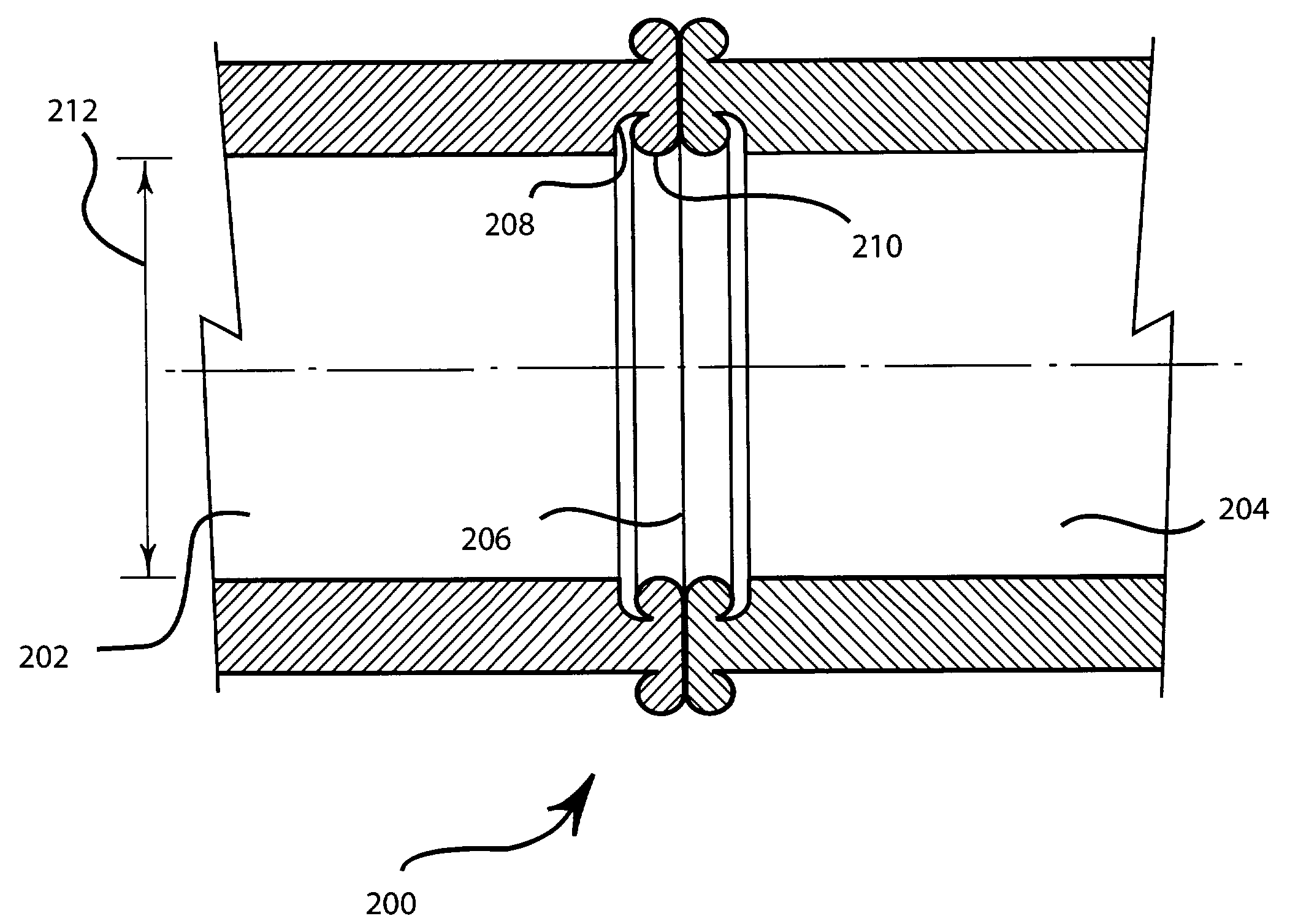
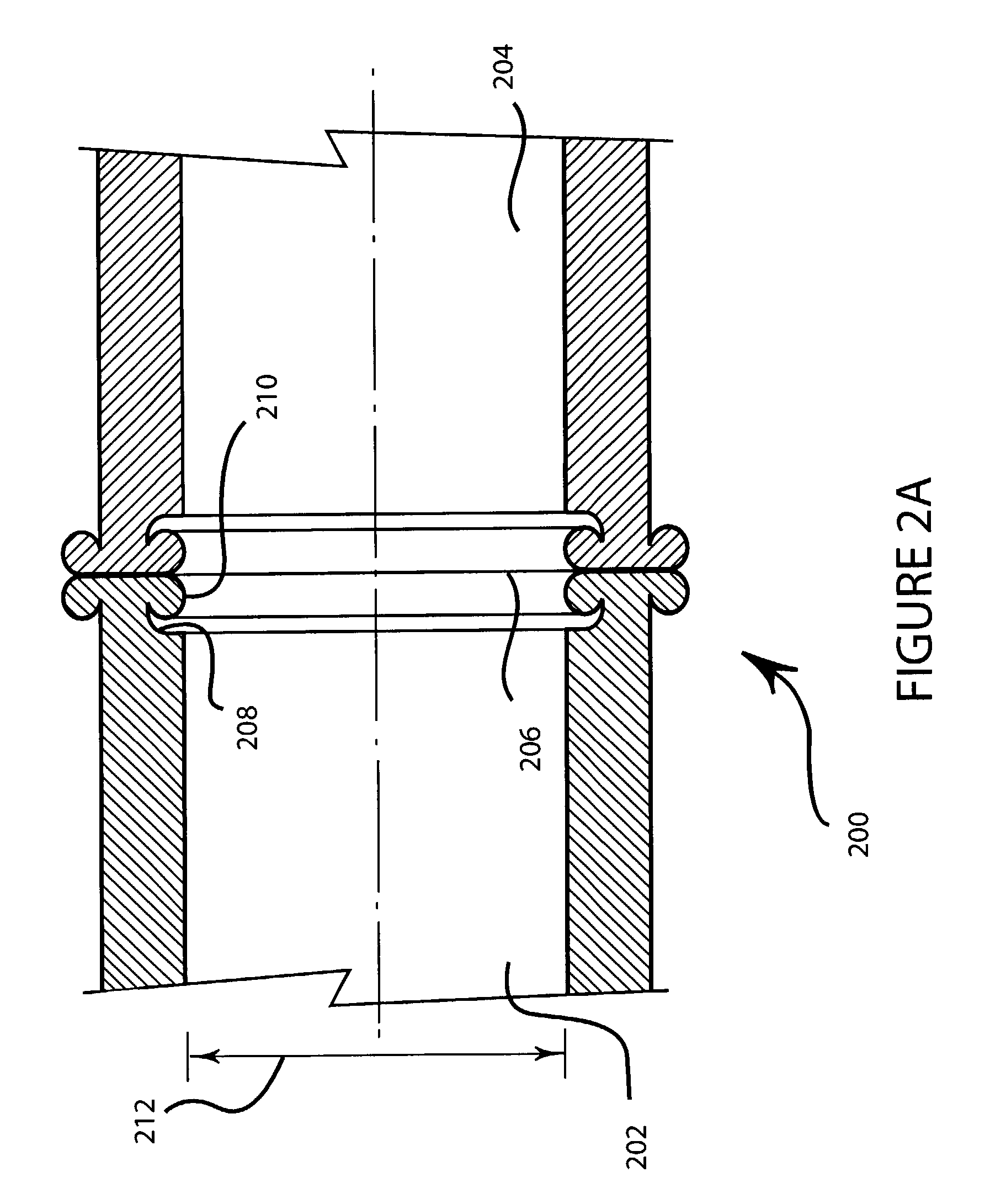
[0037]FIG. 2A illustrates a cross section of embodiment 200 of the present invention wherein a first pipe 202 is joined to a second pipe 204 along the fusion weld line 206. Pipe 202 has an undercut area 208 that allows the inner lip 210 to be recessed below the normal inner diameter 212.

[0038]The recessed area 208 in the present invention is formed during the normal facing operation as explained hereinafter. The shape of the recessed area 208 is selected so that the inner lip 210 may be partially or fully recessed below the inner diameter 212 of the pipe. The recessed lip allows fluids to flow through past the joint with a minimum of obstruction to collect solids and other items such as in sewer applications. In other applications, the recessed lip allows a bundle of wires, fiber optic cables, or other conductors to use the full inner diameter of the pipe. When the pipe is used as a protective conduit, the recessed lips may make it easier to install the cables or transmission lines,...

embodiment 300

[0042]FIG. 3A illustrates a cross section of embodiment 300 of the present invention wherein a first pipe 302 is joined to a second pipe 304 along the fusion weld line 306. Pipe 302 has a beveled area 308 that allows the inner lip 310 to be recessed below the normal inner diameter 312.

[0043]FIG. 3B illustrates a cross section of embodiment 300 of the present invention showing pipe 302 prior to welding. Beveled area 308 is shown in this view.

[0044]Embodiment 300 is similar to embodiment 200 in all aspects except that the shape of the recessed area is varied. Various shapes for the recessed area may be developed by those skilled in the art while maintaining within the scope and intent of the present invention. For example, bevels of various angles and depths may be used. Curved, straight, angled, or other shaped sections may also be used.

[0045]FIG. 4A illustrates a cross section of a first section of pipe 402 and a second section of pipe 404 prior to welding. The sections of pipe 402 ...

embodiment 700

[0061]FIG. 7A illustrates a cross section of embodiment 700 of the present invention wherein a first pipe 702 is joined to a second pipe 704 along the fusion weld line 706. Pipe 702 has a beveled area 708 that allows the outer lip 710 to be recessed below the normal outer diameter 712.

[0062]FIG. 7B illustrates a cross section of embodiment 700 of the present invention showing pipe 702 prior to welding. Beveled area 708 is shown in this view.

[0063]The embodiment 700 is applicable to applications where the lips on the exterior side of the pipe are problematic, such as when the assembled pipe is handled through a conveyor mechanism, feeding mechanisms, transportation devices, or other apparatus where a circumferential lip may catch or impede the movement of the pipe. It is common practice to manually cut off the lips after the welding process if the lips are problematic. The present embodiment eliminates the secondary process and hence cost of removing the lips.


PUM

PropertyMeasurementUnit
Lengthaaaaaaaaaa
Thicknessaaaaaaaaaa
Diameteraaaaaaaaaa

Abstract

Disclosed is a method, apparatus, and design of a fusion welded pipe wherein the effects of an inner bead of the fusion weld are minimized. The internal shape of the pipe prior to welding may be configured in several different shapes so that the beads or lips produced by the fusion welding process are unobtrusive and do not interfere with the function of the pipe. In a likewise manner, the outer shape of the pipe prior to welding may be configured so that the lips are unobtrusive on the external surface of the pipe.

Description

CROSS REFERENCE TO RELATED APPLICATIONS[0001]The present application is based upon and claims the benefit of U.S. Provisional Patent Application Ser. No. 60 / 363,126 by William J. Temple entitled “Beveled Cutter” filed Mar. 8, 2002, the entire contents of which is hereby specifically incorporated by reference for all it discloses and teaches.BACKGROUND OF THE INVENTION[0002]a. Field of the Invention[0003]The present invention pertains generally to the fusion of plastic pipe and specifically to the fusion of plastic pipe wherein seams created by the fusion process are minimized.[0004]b. Description of the Background[0005]Polyethylene pipe is used commercially for the construction of pipelines for various applications such as natural gas, water, sewer, and other materials. In addition, polyethylene pipe may be used as conduit to protect transmission cables such as high voltage electricity, fiber optic telecommunication, telephone, cable television, and other signal cables.[0006]Polyeth...

Claims


Application Information

Patent Timeline
IPC IPC(8): B29C57/00B23B5/16B26D3/16B29C65/00B29C65/20
CPCB23B5/167B26D3/166B29C66/02241B29C66/1142B29C66/322B29C66/5221B29C66/1224B29C66/1226B29C66/1228B29C65/2092Y10T156/1082B29C2793/0009B29L2023/22Y10T156/1322Y10T156/1064Y10T156/125Y10T156/1062Y10T156/1066B23B2260/004Y10T83/04B29C66/8414
Inventor TEMPLE, WILLIAM J.
Owner FAST FUSION
Why Eureka
Try Eureka