
Reactor for catalytic gas phase oxidation

Inactive Publication Date: 2006-02-07
NIPPON SHOKUBAI CO LTD
View PDF13 Cites 14 Cited by
  • Summary
  • Abstract
  • Description
  • Claims
  • Application Information

AI Technical Summary

Benefits of technology

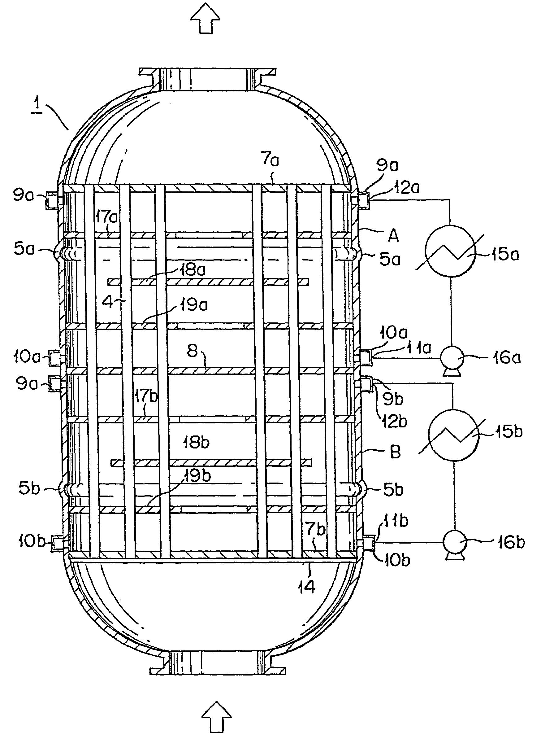
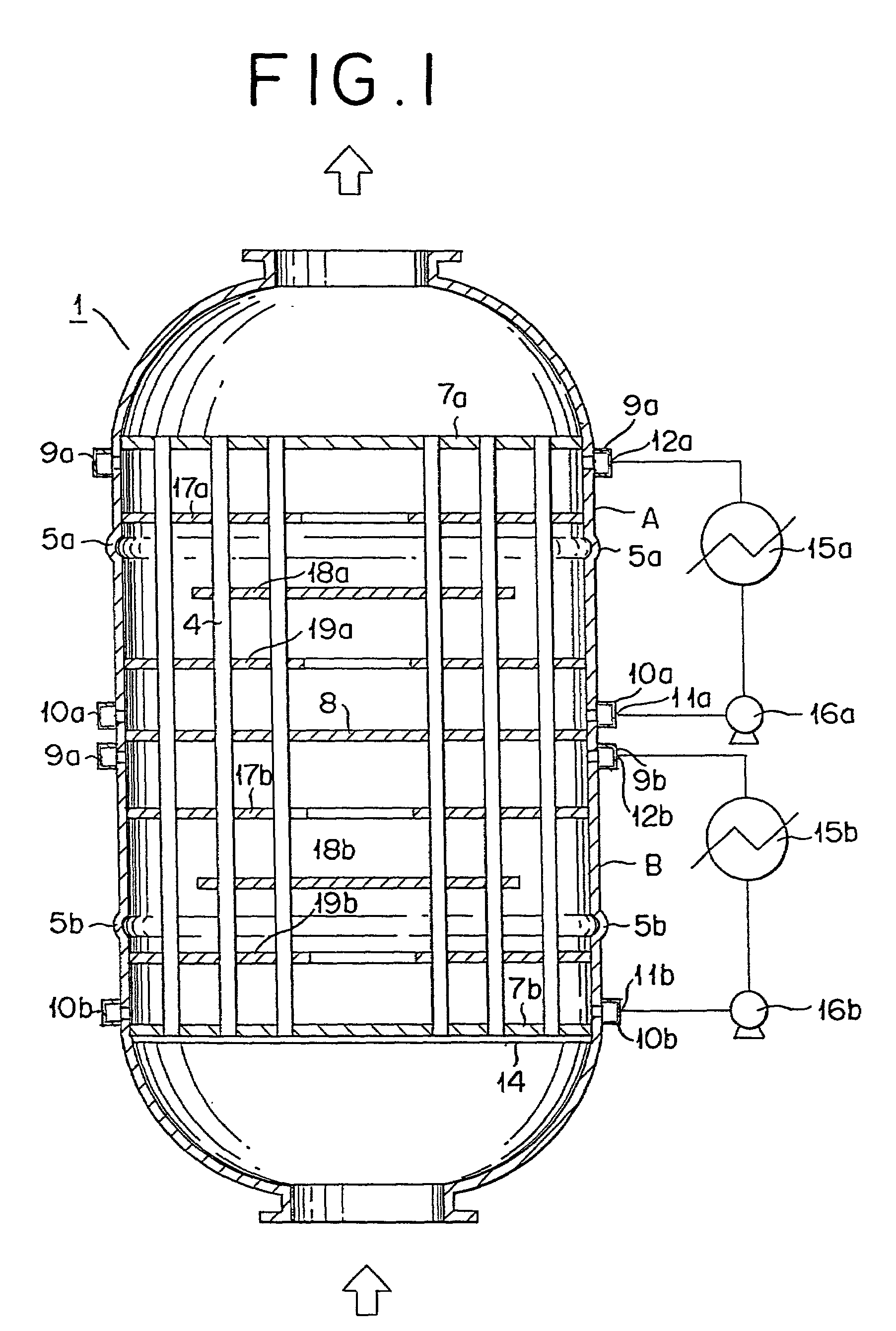
[0010]According to the reactor of this invention, since the intermediate tube sheet substantially seals the upper and the lower chambers and since the chambers are each provided around the shell thereof with the expansion joint, the temperature of the heat medium in each of the chambers can be readily maintained and controlled, the distortion of the reactor by heat can be reduced, and the heat generated by the reaction can be readily absorbed.
[0011]Further, according to the method of this invention, desired products can be produced in a high yield.

Problems solved by technology

Thus, it is not intended to shield the separate chambers substantially completely.
Further, it is mentioned that when the reaction tubes and the shields happen to be fixed in close approximation, any temperature difference between the regions A and B or frequent use of the reactor for heating and cooling will bring disadvantages such as inducing the reaction tubes and the shields to develop thermal strain and suffering them to come into mutual contact and wear away.

Method used


Image

  • Reactor for catalytic gas phase oxidation
  • Reactor for catalytic gas phase oxidation
  • Reactor for catalytic gas phase oxidation

Examples


example 1

[0094]Synthesis of acrylic acid by the oxidation of propylene was performed by the use of a vertical shell-and-tube type reactor equipped with expansion joints, 24 reaction tubes of steel each measuring 6 m in length, 25.0 mm in inside diameter, and 29.0 mm in outside diameter and having an intermediate tube sheet at an intermediate height as illustrated in FIG. 1.

[0095]The amount of water migrating from the upper chamber to the lower chamber through the intermediate tube sheet partitioning these two chambers was 0.1 ml / hour per reaction tube under the condition of a pressure difference of 39226.6 Pa (0.4 kg / cm2). Then, the amount of water migrating from the lower chamber to the upper chamber through the intermediate tube sheet partitioning these two chambers was 0.1 ml / hour per reaction tube under the condition of a pressure difference of 39226.6 Pa (0.4 kg / cm2). In the hydraulic test, the relation, amount of leakage (ml / hour per reaction tube)≦1.27×10⁻⁵×pressure difference (Pa) {1...

example 2

[0105]Synthesis of methacrylic acid by the oxidation of isobutylene was performed by the use of a vertical shell-and-tube type reactor equipped with 24 reaction tubes of steel each measuring 6 m in length, 25.0 mm in inside diameter, and 29.0 mm in outside diameter and having an intermediate tube sheet at an intermediate height as illustrated in FIG. 1.

[0106]The amount of water migrating from the upper chamber to the lower chamber through the intermediate tube sheet partitioning these two chambers was 0.1 ml / hour per reaction tube under the condition of a pressure difference of 39226.6 Pa (0.4 kg / cm2). Then, the amount of water migrating from the lower chamber to the upper chamber through the intermediate tube sheet partitioning these two chambers was 0.1 ml / hour per reaction tube under the condition of a pressure difference of 39226.6 Pa (0.4 kg / cm2). In the hydraulic test, the relation, amount of leakage (ml / hour per reaction tube)≦1.27×10⁻⁵×pressure difference (Pa) {1.25×pressure...


PUM

PropertyMeasurementUnit
Fractionaaaaaaaaaa
Fractionaaaaaaaaaa
Fractionaaaaaaaaaa

Abstract

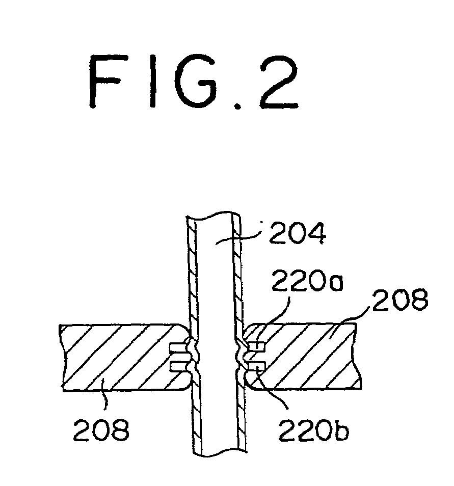
In a shell-and-tube type reactor, the leakage between the upper and lower chambers is substantially decreased by tightly fitting the reaction tubes to the shield. The present invention provides a reactor for use in catalytic gas phase oxidation characterized by expanding reaction tubes to at least one groove formed in the reaction tube-fixing part of an intermediate tube sheet to form a shield, thereby forming plural of chambers with the intermediate tube sheet, and forming an expansion joint around the periphery of each of the chambers.

Description

BACKGROUND OF THE INVENTION[0001]1. Field of the Invention[0002]This invention relates to a shell-and-tube heat exchanger type reactor having the interior of the shell thereof partitioned into a plurality of chambers, and to a method for the production of (meth)acrylic acid by the use of the reactor. More particularly, it relates to a shell-and-tube heat exchanger type reactor adapted to repress migration of a heat medium (heat transfer medium) between adjacent chambers partitioned with a shield, and to a method for the production of (meth)acrylic acid by the use of the reactor.[0003]2. Description of the Related Art[0004]Generally, a method for producing acrylic acid by the reaction of catalytic gas phase oxidation of propylene entails generation of a large amount of heat. For the purpose of controlling the reaction temperature within a fixed range or preventing the occurrence of hot spots (local spots of abnormally high temperature in the catalyst layer) within a reaction zone, a ...

Claims


Application Information

Patent Timeline
IPC IPC(8): B01J8/04B01J8/00B01J8/06B01J12/00B01J19/00C07B61/00C07C51/25C07C57/05F28D7/00F28D7/16
CPCB01J8/008B01J8/067F28D7/0066F28D7/0091C07C51/252C07C57/04B01J2208/00212B01J2208/00221B01J2208/025F28F2265/26B01J8/06
Inventor NISHIMURA, TAKESHIMORI, MASAKATSUKITAURA, MASATSUGUDODO, OSAMUTANIMOTO, MICHIO
Owner NIPPON SHOKUBAI CO LTD
Learn More