Relaxation oscillator for transponder

a technology of relaxation oscillator and transponder, which is applied in the direction of burglar alarm mechanical actuation, instruments, transportation and packaging, etc., can solve the problems of poor road handling, excessive tire wear, poor gasoline mileage,

Inactive Publication Date: 2006-02-07
THE GOODYEAR TIRE & RUBBER CO
View PDF42 Cites 18 Cited by
  • Summary
  • Abstract
  • Description
  • Claims
  • Application Information

AI Technical Summary

Benefits of technology

[0050]According to an aspect of the invention, a method is described for generating an oscillating measurement signal in an RF transponder such as described hereinabove, wherein the frequency of the oscillating measurement signal is indicative of a measured parameter. The method primarily consists of alternately directing the measurement current for charging the measurement capacitor, and then directing a mirrored measurement current for discharging the measurement capacitor in each measurement switching circuit of the relaxation oscillator. The measurement switching circuits can be supplied with measurement currents programmably scaled

Problems solved by technology

Operating the vehicle with low tire pressure may result in excessive tire wear, steering difficulties, poor road-handling, and poor gasoline mileage, all of which are exacerbated when the tire pressure goes to zero in the case of a “flat” tire.
Some proposed systems have relatively complex transponder-sensor capabilities, including measurement and reporting of tire rotations and speed, along with tire ID, temperature, and pressure.
The environment within which a tire-mounted transponder must reliably operate, including during manufacture and in use, presents numerous challenges to the successful operation of the transducer.
Although it is generally well known to use pressure transducers in pneumatic tires, in association with electronic circuitry for transmitting pressure data, these pressure-data systems for tires have been plagued by difficulties inherent in the tire environment.
Such difficulties include effectively and reliably coupling RF signals

Method used


Image

  • Relaxation oscillator for transponder
  • Relaxation oscillator for transponder
  • Relaxation oscillator for transponder

Examples


Embodiment Construction

[0069]As mentioned hereinabove, it is an object of the present invention to provide a system for monitoring vehicle tire pressure and warning the driver when a low tire inflation pressure condition occurs.

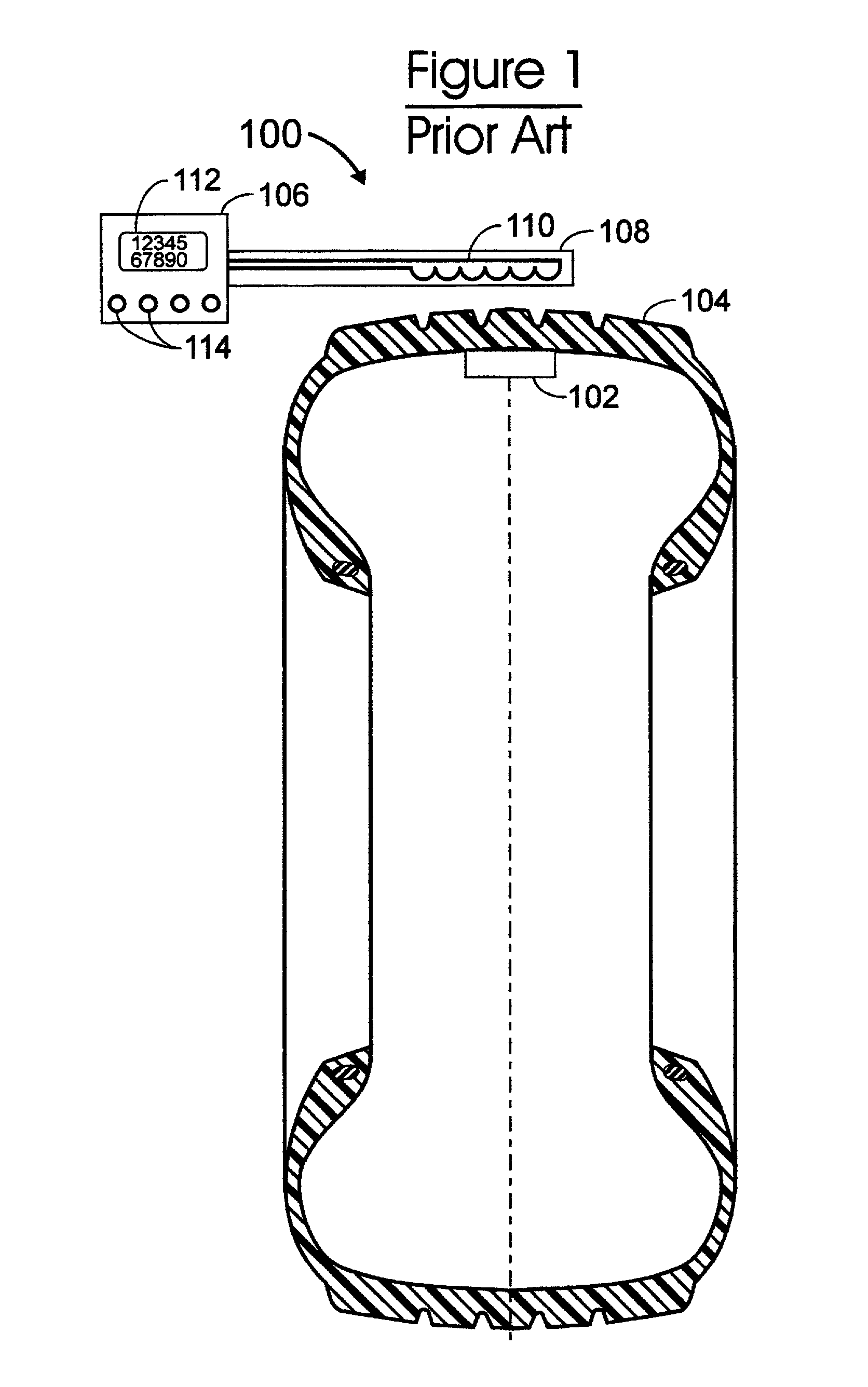
[0070]FIG. 1 illustrates an RF transponder system 100 of the prior art, comprising an RF (radio frequency) transponder 102 disposed within (e.g., mounted to an inner surface of) a pneumatic tire 104. (An antenna, not shown, is mounted within the tire 104 and is connected to the transponder 102.) The transponder 102 is an electronic device, capable of transmitting an RF signal comprising unique identification (ID) information (e.g., its own serial number, or an identifying number of the object with which it is associated -in this example, the tire 104) as well as data indicative of a parameter measurement such as ambient pressure sensed by a sensor (not shown) associated with the transponder 102 to an external reader / interrogator 106. The external reader / interrogator 106 provides an...


PUM


Abstract

A relaxation oscillator for a transponder capable of measuring one or more parameters (e.g., temperature, pressure) in an object and transmitting a data stream to an external reader/interrogator. The transponder typically operates in a passive mode, deriving its power from an RF interrogation signal received by an antenna system, but c=also operate in a battery-powered active mode. The transponder includes memory for storing measurements, calibration data programmable trim settings, transponder ID and the like. Measurement readings comprise counting oscillations of a measurement signal during a fixed time window. The measurement signal is generated by a relaxation oscillator driven by the alternating charging and discharging of measurement capacitors. wherein the capacitor charging rate is a function of current, and of capacitance. By using a mirror measurement current lo discharge the measurement capacitors, the discharge rate is made approximately equal to the charge rate. The measurement current can be scaled according to programmed trim settings to independently optimize readings for the different measured parameters.

Description

CROSS-REFERENCE TO RELATED APPLICATIONS[0001]This application is a national stage entry of PCT / US 99 / 29890 entitled “Relaxation Oscillator For Transponder” filed Dec. 15, 1999.[0002]This application relates to PCT applications Serial no. PCT / US99 / 29723 entitled POWER ON RESET FOR TRANSPONDER, Serial No. PCT / US99 / 29827, entitled PROGRAMMABLE MODULATION INDEX FOR TRANSPONDER and Serial No. PCT / US99 / 29840 entitled PROGRAMMABLE TRIMMING FOR TRANSPONDER, each having a filing date concurrent with that of the present application.[0003]This application is a continuation-in-part of commonly-owned, copending PCT application Serial Nos. PCT / U99 / 29668 and PCT / US99 / 29606 both filed on 14 Dec. 1999, which in turn are continuation-in-part of commonly-owned, copending PCT application Serial Nos. PCT / US98 / 07338, PCT / US99 / 07836 and PCT / US99 / 07575 all filed on 14 Apr. 1998.[0004]This application claims the benefit of U.S. Provisional Patent Application No. 60 / 134,455, filed May 17, 1999 by Yones.TECHN...

Claims


Application Information

Patent Timeline
IPC IPC(8): G08B13/14
CPCB60C23/0433B60C23/0462
Inventor YONES, DALE LEE
Owner THE GOODYEAR TIRE & RUBBER CO
Why Eureka
Try Eureka