Rotating chains or rings carry vertically hanging trays for heat processes in a furnace

a technology of rotating chains or rings and heat processes, which is applied in the direction of furnaces, domestic stoves or ranges, charge manipulation, etc., can solve the problems of energy waste, excessive energy waste, and limited conventional furnaces, so as to reduce inert gas consumption, minimize heat loss, and simplify loading/unloading procedures

Active Publication Date: 2006-02-14
TANG CHING CHIANG
View PDF9 Cites 4 Cited by
  • Summary
  • Abstract
  • Description
  • Claims
  • Application Information

AI Technical Summary

Benefits of technology

[0007]It is therefore an object of the present invention to provide a new and improved furnace configuration to simplify the loading / unloading procedures, to minimize the heat losses and to reduce the inert gas consumption such that the above-mentioned limitations and difficulties of the conventional furnace can be resolved.
[0008]Specifically, it is an object of the present invention to provide a furnace enclosed in a furnace housing to enable a substantially vertical rotational movement of objects within the furnace housing to carry out different kinds of heat processes and cooling processes in a single processing cycle. Special mechanical designs are implemented to assure the objects for heating are maintained at a fixed orientation without slipping or position shifts. The losses of heat applied for performing the heat processes are significantly reduced because the loading and unloading processes can be carried out only once at the same location. Efficient utilization of energy is enhanced, as the heating zone is located on the top portions of the furnace where the hot air generated by the properly arranged heater around the rotating cycle path migrates through natural convention to the top of the chamber with few electric fans. This invention thus takes advantage of the natural convection to reduce the energy consumption compared to the conventional furnace applying more electric fans as means of force convention.
[0009]In a vertical rotating system as now disclosed in this invention, one person is enabled to carry out both the loading-unloading operations and temperature profile adjustment all at one location. Additional benefit is realized because the heat generated by lower section in the oven is available at other portions of the furnace at a higher level within the furnace by its own natural convection or partial force convection to further enhance the effectiveness of the heating processes.

Problems solved by technology

The conventional furnaces are still limited by the technical difficulties that linear conveyors are often employed to carry the objects through a furnace to perform several cycles of heating and cooling processes through several chambers or zones.
In the conventional configuration, there are excessive energy wastes due to heat losses caused by the hot air leaks from the multiple openings in heat chambers to accommodate the entry and exit of the linear conveyers.
Also energy is wasted due to the inefficiency of heat utilization as the hot air continuously migrates to the top of the heat chamber while the objects for heating processes are passed through the bottom of the heating chambers.
Furthermore, in a batch process, when the cooling and heating processes are performed in a single chamber, the heating and cooling cycles often prolong the manufacturing processes because the processing cycles requires minimum lengths of time for the objects to cool down and pre-heat before a next heating cycle may begin.
All these limitations add to the cost and manufacture complexities when a conventional furnace is employed.
The heat generated at each chamber cannot be easily recovered and used again by other chambers unless a special and more costly heat recycle designs are implemented to improve the energy recycling.
Another limitation of the patented invention is the limited amount of reduction that can be accomplished in reducing the inner gas consumption by installing the necessary partitions as disclosed in this patent.
Other drawback of the linear type furnace is the limitation that such furnaces are not suitable for application in offices or laboratories due to the volume occupied by the furnace.
Due to the required space, installation of a furnace in a medical laboratory or restaurant for food processes is not feasible even that such furnace would be quite convenient and useful for heat treatments.
Consequently, the heat applied in the previous batch operation is lost, so does the inert gas pumped into the chambers of the furnace.

Method used


Image

  • Rotating chains or rings carry vertically hanging trays for heat processes in a furnace
  • Rotating chains or rings carry vertically hanging trays for heat processes in a furnace
  • Rotating chains or rings carry vertically hanging trays for heat processes in a furnace

Examples


Embodiment Construction

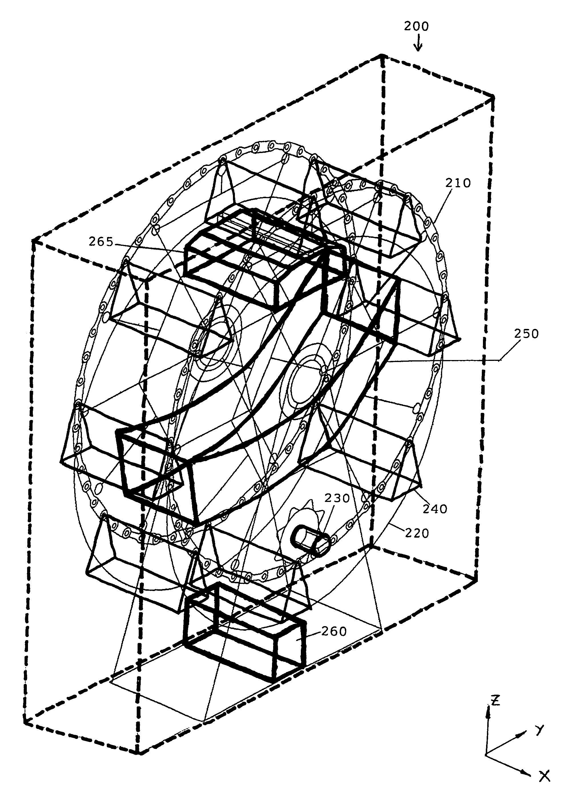
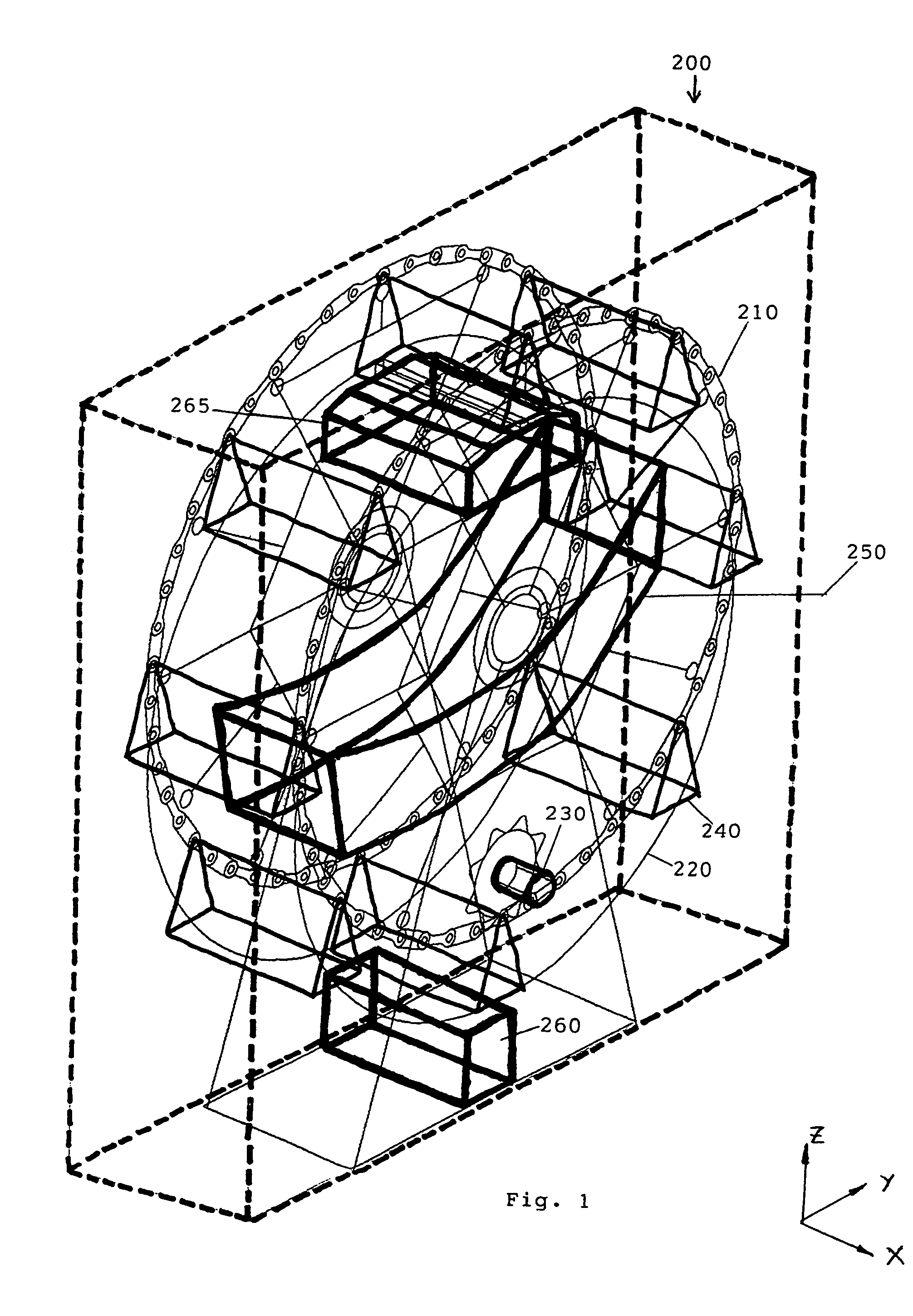
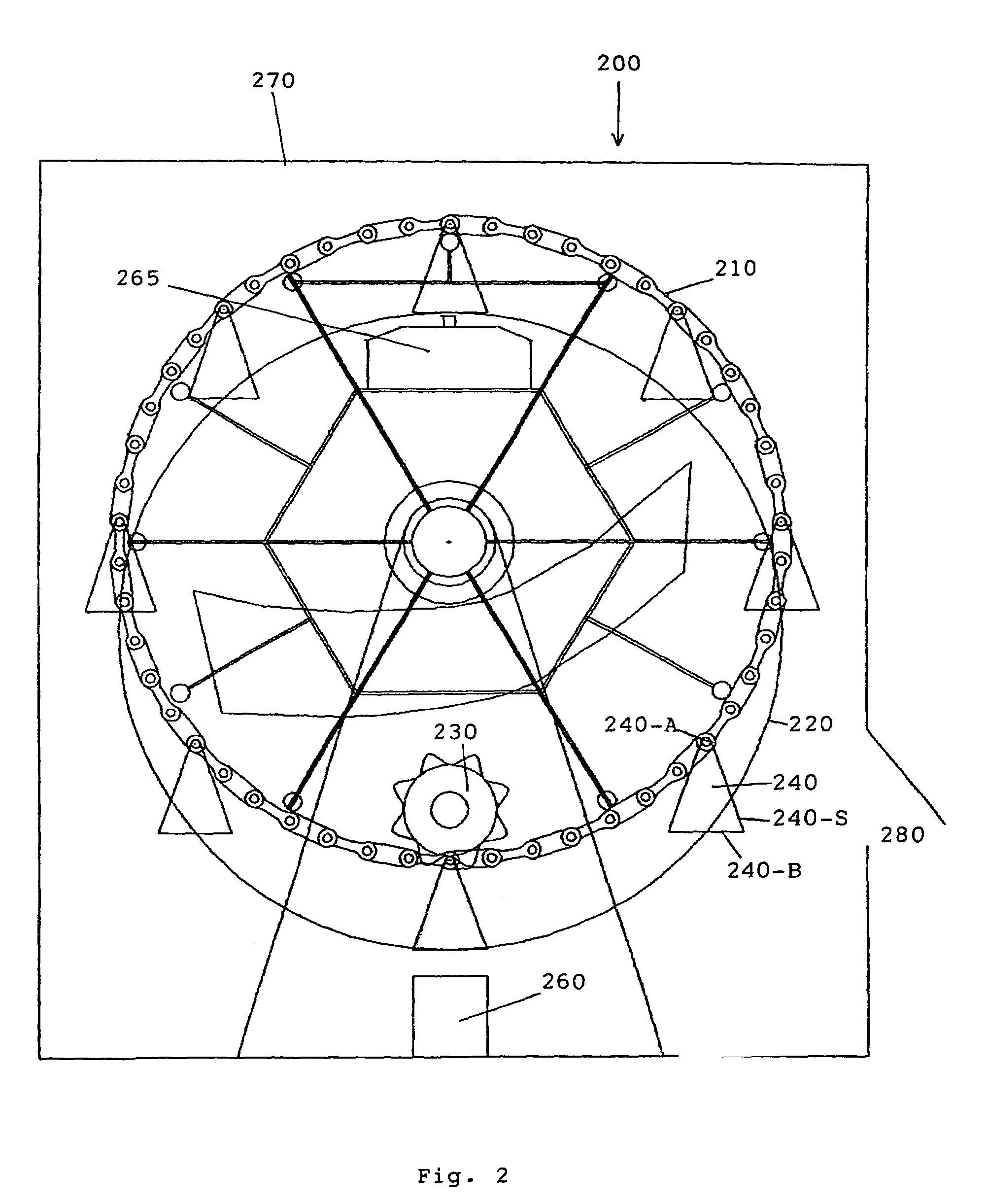
[0019]Referring to FIGS. 1 and 2 respectively for a perspective view and a front view of a furnace 200 of this invention. The furnace includes a pair of chains 210 and a pair of rings 220 disposed immediately below the pair of chains 210. A motor 230 with gearbox is engaged to one chain or both chains to drive the pair of chains to rotate while the pairs of rings 220 are kept stationary. A plurality of trays 240 that includes a horizontal bottom plate 240-B and side panels 240-S with top apex 240-A having two hanging points attached and hung on the chains 210. The bottom plate 240-B is engaged and restrained along the pair ring 220 to assure that the horizontal bottom plate is continuously maintained at a horizontal plane as the pairs of chains 210 carry the trays 240 along a rotational trajectory. The trays 240 are engaged between the pairs of rotational chains 210 and the stationary rings 220 employing a “four bar linkage” mechanism such that the bottom plate 240-B can always orie...


PUM

PropertyMeasurementUnit
shapeaaaaaaaaaa
temperaturesaaaaaaaaaa
heat lossesaaaaaaaaaa

Abstract

A furnace for energy saving and space reduction used in electronic industry assembly, medical sterilization, or food process application is provided. In the furnace there is a number of trays hinged on a pair of continuous chains which movement is in a circle or oval trajectory, or on the rotating beam mechanism constituting as spider web form. A pair of rings is added to restrain the swing movement of each tray via the mechanical linkage during rotation. A dome formed at the top portion inside the furnace is used as an enclosure where the heated inert gas is almost kept. The electric power for heater and blower can be reduced by the natural convection. An opening is located at the lower portion of the furnace; so the operator can do loading and unloading performance.

Description

BACKGROUND OF THE INVENTION[0001]1. Field of the Invention[0002]This invention relates generally to a furnace configuration by arranging the mechanical and electric units to carry out heating-cooling processes for electronic component manufacturing, food process, or medical sterilization applications. More particularly, this invention relates to a new and improved furnace configuration to simplify the processes for manufacturing electronic component, for food processing, or for carrying out medical sterilization applications while reducing wastes of energy and achieving time-saving required for the processes.[0003]2. Description of the Related Art[0004]The conventional furnaces are still limited by the technical difficulties that linear conveyors are often employed to carry the objects through a furnace to perform several cycles of heating and cooling processes through several chambers or zones. Specifically, the conventional furnaces used in the electronic industry for processing a...

Claims


Application Information

Patent Timeline
Patent Type & Authority Patents(United States)
IPC IPC(8): F27D3/12B23K1/008
CPCB23K1/008B23K2201/42B23K2101/42
Inventor TANG, CHING CHIANG
Owner TANG CHING CHIANG
Why Eureka
Try Eureka