Variable-speed control system for a transmission

Inactive Publication Date: 2006-02-14
TOKYO JIDO KIKO
View PDF22 Cites 24 Cited by
  • Summary
  • Abstract
  • Description
  • Claims
  • Application Information

AI Technical Summary

Benefits of technology

[0010]A fifth object of the present invention is to provide a pulley pressure control system capable of simultaneously applying a pressing force and a semi-elastic force, the elastic vibration of which is substantially restrained by t

Problems solved by technology

The belt type transmissions proposed by the above patents disclose cam compensation; however, the cam is recovered due to the release of pressure upon the skip motion, resulting in inappropriate operation.
On the other hand, even if the transmission is artificially controlled only by a pressing force with the use of an automatic control system that involves a time delay inherently, it is realistically impossible to recover the appropriate frictional force momentarily, so that the quick responsibility will not be attained.
However, there remain some outstanding problems.
First, although the follower function side is able to control th

Method used


Image

  • Variable-speed control system for a transmission
  • Variable-speed control system for a transmission
  • Variable-speed control system for a transmission

Examples


first embodiment

[First Embodiment]

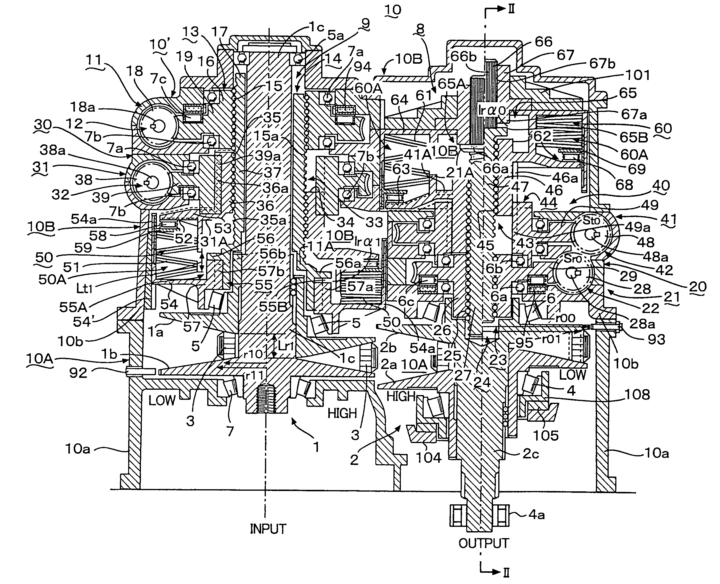
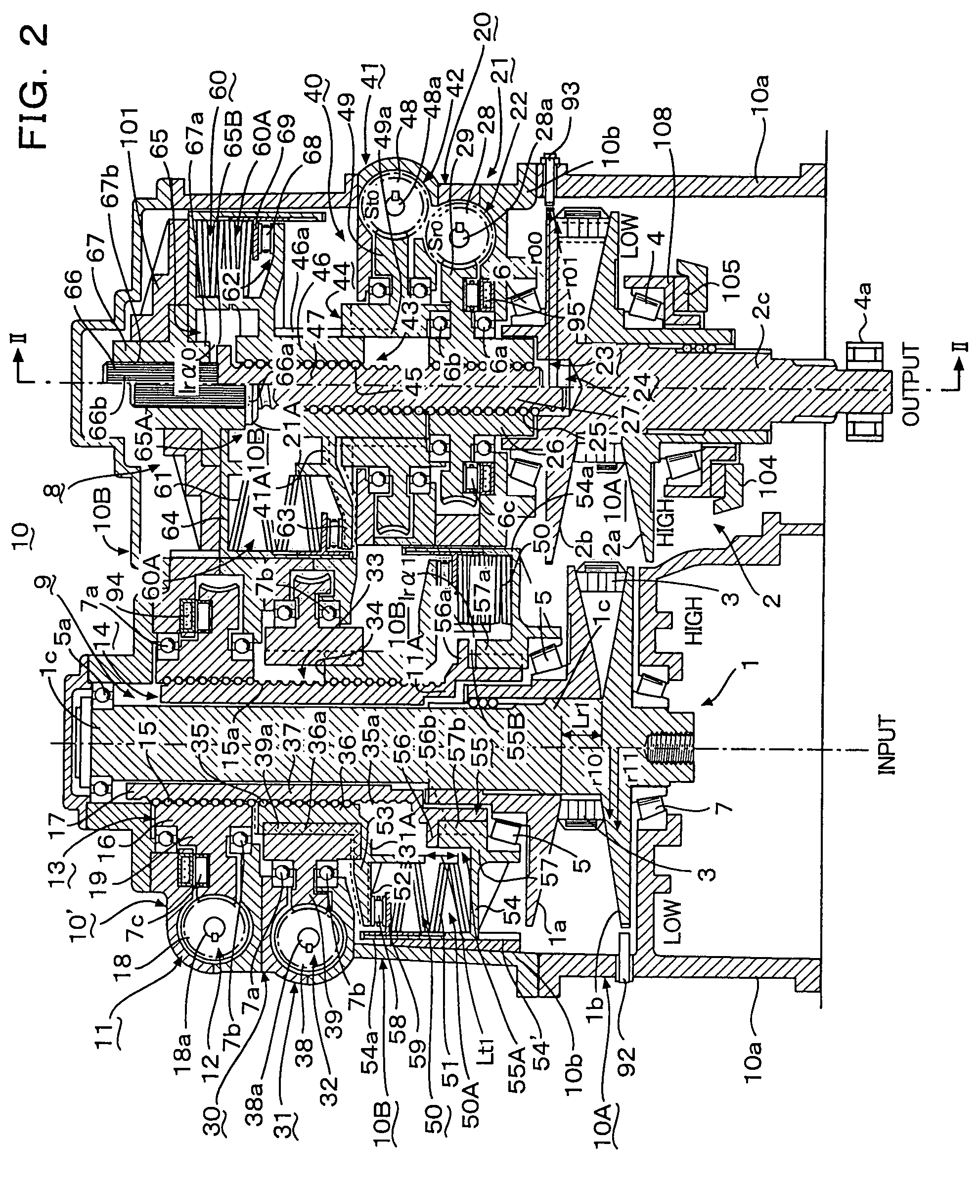
[0051]Referring to FIGS. 2 to 7, there is shown a continuously variable transmission 10 to which a pulley pressure control system 10B is applied according to a first embodiment of the present invention. The continuously variable transmission 10 includes a variable-speed transmission apparatus 10A having an input primary pulley (driving pulley) 1, an output secondary pulley (driven pulley) 2, and a press type belt 3 wound around the primary and secondary pulleys 1 and 2, and the pulley pressure control system 10B, which is a variable-speed control system for a transmission for controlling, by means of a control unit 90 shown in FIG. 4, an primary pulley pressure control system 9 and an secondary pulley pressure control system 8 disposed on one plane. In this embodiment, an input side pressure application device 10′ includes an input compound compressing device 30, an input elastic device 50, an input engagement device 55, and two input driving sources 71 and 75. Ano...

second embodiment

[Second Embodiment]

[0085]A pulley pressure control system according to a second embodiment will be described below. FIG. 8 shows a pulley pressure control system 10B according to the present embodiment the configuration of which is the same as that of the first embodiment. However, this embodiment is different from the first embodiment in that the belt 3 is not the press-type but the pull-type. Both the pressure application devices 10′ and 20 differ from each other in a control manner, but do not have modified configurations. Therefore, like or corresponding parts are denoted by the same reference characters and the duplicated description thereof will be omitted.

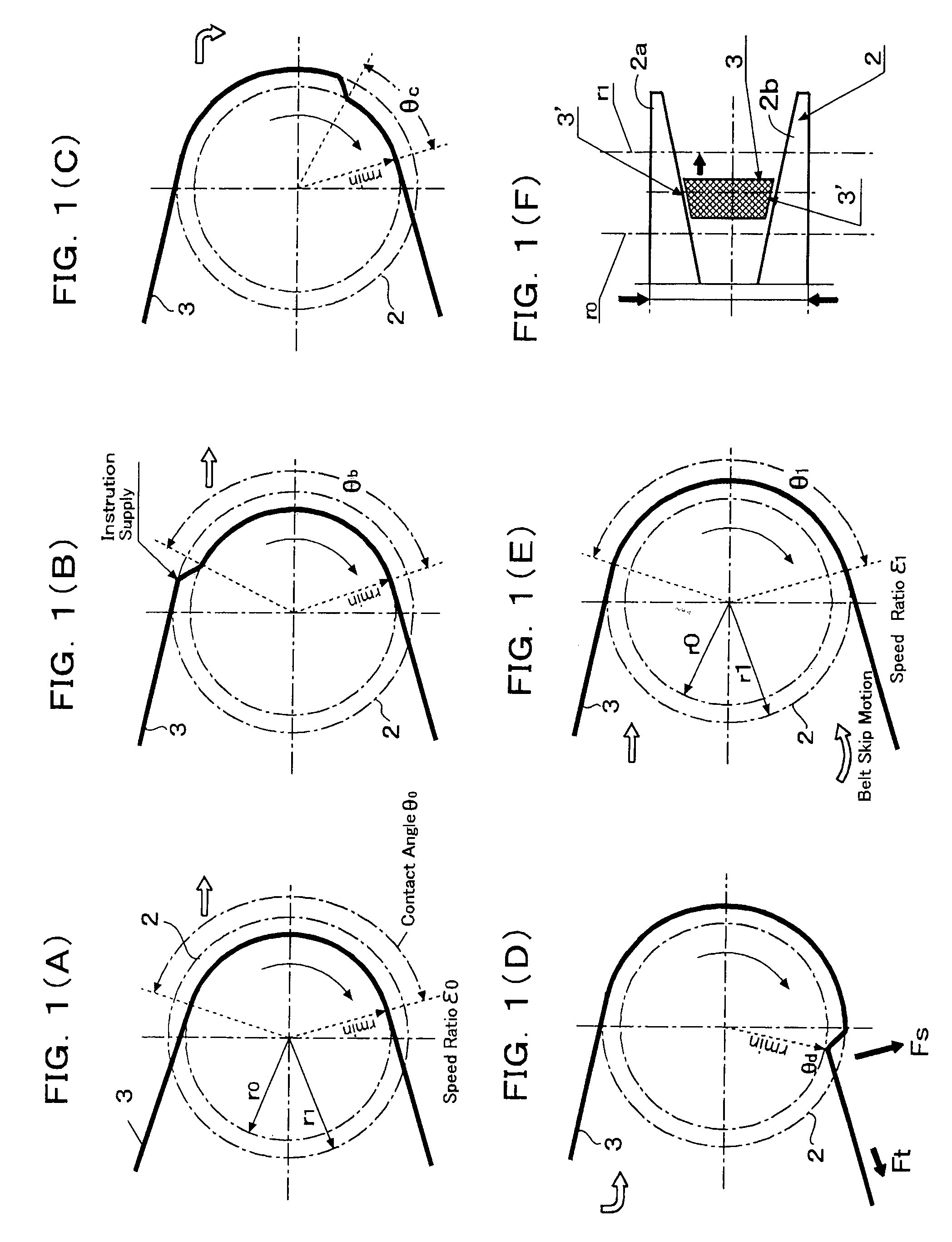
[0086]As shown in FIG. 9A, when a large elastic force is applied to the pulley 2 and the belt 3 in the low-speed range, an increase in the contact area between the belt 3 and a driven pulley (secondary pulley) 2 causes an excessive frictional force. Then, at a radius r0, the belt 3 tends to be brought into a wound state in a...

third embodiment

[Third Embodiment]

[0088]A third embodiment according to the present invention will be described below with reference to FIG. 10A, which is a sectional view of a pressure application device 10′, with the left half thereof illustrated. In the first embodiment, the primary and secondary compressing devices 14 and 34 share the use of the sliding member 17 as shown in FIG. 2. On the other hand, in this embodiment, the primary and secondary compressing devices 14 and 34 operate individually. As shown in FIG. 10A, the secondary compressing device 34 can be wholly pressed by a pressing projection 17c provided on the sliding member 17 of the primary compressing device 14. The sliding members 36 and 37 have splines 36a and 37a, respectively. Thus, the pressing end of the compound compressing device 30 includes the direct pressing end 11A of the primary compressing device 14 and the superposing pressing end 31A wherein the pressures of the primary and secondary compressing devices 14 and 34 ar...


PUM


Abstract

In a constant horse-power type continuously variable transmission, a pressing force supply path using for a rotation-speed control is supplied to one of an input pulley d an output pulley, and an elastic force supply path using for an axial torque control to the then. However, the one pulley is applied only the pressing force as a control element, although the torque of the other pulley can be regulated by the elastic force, so that the frictional force applied to said one pulley cannot be positively regulated, and consequently, axial torque controls of an input shaft and an output shaft cannot be achieved sufficiently. This effect causes the transmission efficiency to deteriorate at both end ranges of a variable speed range. In the present invention, a variable-speed control system for a transmission makes axial torque controls of both the input and output pulleys compensate and hold a low-speed range and/or a high-speed range into a higher transmission efficiency, while cooperating with the semi-elastic force to the one pulley, of which elastic vibration is suppressed by the pressing force thereto to half, and the elastic force to the other pulley. By this way, a band width of an entire transmittable speed range is substantially enlarged.

Description

CROSS-REFERENCE TO RELATED APPLICATIONS[0001]This application is a divisional application of application Ser. No. 10 / 004,881 filed Dec. 7, 2001 now U.S. Pat. No. 6,764,421, the disclosure of which is incorporated herein by reference in its entirety.BACKGROUND OF THE INVENTION[0002]The present invention relates to a pulley pressure control system for a transmission which controls a pressing force and an elastic force applied to a pulley to stabilize torque and achieve high efficient transmission, which is applicable to general industrial machines, vehicles, electric motors and the like.[0003]A constant horse power transmission is known from U.S. Pat. Nos. 4,973,288 and 5,269,726; the former discloses a hydraulic type and the latter a screw pressurizing type. The inventive concepts of both the patents have a principal defect. FIGS. 1(A) to 1(F) are views of assistance in explaining the principle of transmission in a belt type transmission. The figures show in the order of (A) to (E) c...

Claims


Application Information

Patent Timeline
IPC IPC(8): F16H61/00F16H9/18F16H55/56F16H61/662F16H63/06
CPCF16H55/56F16H61/66272F16H63/065F16H63/062F16H2059/186F16H9/18
Inventor ONOGI, KENKICHI
Owner TOKYO JIDO KIKO
Why Eureka
Try Eureka