Battery having a sheet current collector fluid-tightly separating basic cells

a collector fluid and battery technology, applied in the field of batteries and electric double layer capacitors, can solve the problems of insufficient size reduction and difficult size reduction of products, and achieve the effects of preventing corrosion of terminals, reducing volume, and improving volumetric efficiency

Inactive Publication Date: 2006-02-14
NEC ENERGY DEVICES LTD
View PDF20 Cites 7 Cited by
  • Summary
  • Abstract
  • Description
  • Claims
  • Application Information

AI Technical Summary

Benefits of technology

[0029]According to the present invention, a plurality of basic cells can be electrically laminated in series via current collectors without using a gasket, and the laminate can be packaged and sealed using a laminated sheet as an outer package material. The number of the laminated basic cells may be appropriately determined to provide a battery or electric double layer capacitor having an required cell voltage or capacit

Problems solved by technology

Thus, an increased voltage requires connecting a plurality of cells in series outside the package, which make

Method used


Image

  • Battery having a sheet current collector fluid-tightly separating basic cells
  • Battery having a sheet current collector fluid-tightly separating basic cells
  • Battery having a sheet current collector fluid-tightly separating basic cells

Examples


example 1

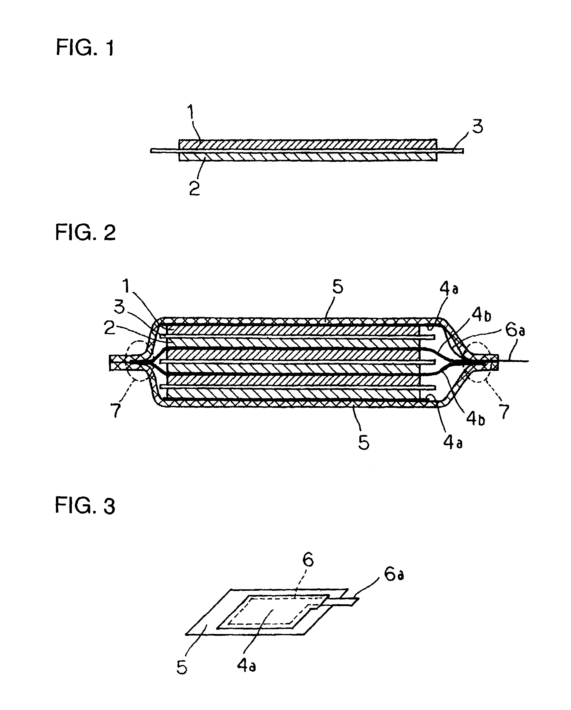
[0052]In this example, a battery shown in FIG. 2 was fabricated, which had a laminated structure of three basic cells in series.

[0053]As a cathode 1, a 10 cm2 solid electrode was formed by adding a conduction aid and a binder to a cathodic active material, the indole trimer represented by chemical formula (1) (R at 5-position in the indole unit is —CN and the remaining Rs are —H: 5-cyanoindole trimer); stirring and blending the mixture by a blender to give an electrode powder; placing 0.5 g of the powder in a mold; and pressing it by a hot press.

[0054]As an anode 2, a 10 cm2 solid electrode was formed by adding a conduction aid to an anodic active material, the polyphenylquinoxaline represented by chemical formula (2); stirring and blending the mixture by a blender to give an electrode powder; placing 0.5 g of the powder in a mold; and pressing it by a hot press.

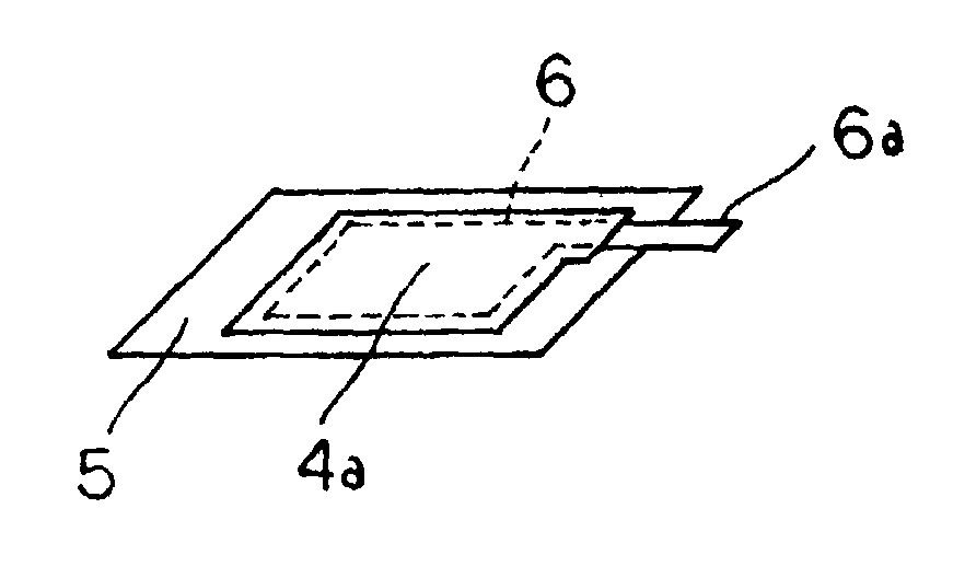
[0055]Current collectors 4a, 4b were conductive rubber sheets and laminated sheets 5 were laminates of an aluminum foil an...

example 2

[0062]A battery was fabricated as described in Example 1, except that an electrode weight was 1.0 g for both cathode and anode.

[0063]A volumetric efficiency of the battery of Example 2 was 87.5%. An ESR for the battery was 120 mΩ. A time taken until sealing in the battery production was 20 min. In the configuration of this example, a volumetric efficiency was improved; a cell ESR could be reduced; and a production time could be reduced.

example 3

[0064]A battery was fabricated as described in Example 1, except that ten basic cells were laminated in series and sealed.

[0065]A volumetric efficiency of the battery of Example 3 was 90.5%. An ESR for the battery was 200 mΩ. A time taken until sealing in the battery production was 20 min. In the configuration of this example, a volumetric efficiency was improved; a cell ESR could be reduced; and a production time could be reduced.


PUM


Abstract

A small battery and an electric double layer capacitor exhibit adequate cell voltage and capacitor withstand voltage. Specifically, the battery or electric double layer capacitor includes basic cells having a pair of electrodes oppositely laminated via the separator, and an electrolyte are packaged in a resin sheet package. The basic cells are laminated in series via a sheet current collector. The sheet current collector extends to an edge of the resin sheet package around the periphery of the basic cells laminated on both sides of the current collector. The sheet current collector is glued or fused to the resin sheet in its edge. The adjacent basic cells via the sheet current collector are fluid-tightly separated within the resin sheet package.

Description

BACKGROUND OF THE INVENTION[0001]1. Field of the Invention[0002]This invention relates to a battery and an electric double layer capacitor which are packaged in a resin sheet.[0003]2. Description of the Related Art[0004]Recent downsizing and weight reduction of mobile devices in information communication applications have led to intensive attempts to develop smaller and lighter batteries and electric double layer capacitors while being capable of rapid charge / discharge.[0005]For meeting the needs for smaller and lighter batteries and electric double layer capacitors, it has been proposed to use a laminated film composed of a polymer film layer and a metal foil layer as an outer package material. For improving rapid charge / discharge properties, a metal plate made of, for example, copper having a smaller electric resistance is employed as a terminal.[0006]Japanese Laid-open Patent Publication No. 8-83596 has disclosed a thin card battery wherein a closed battery package consisting of ...

Claims


Application Information

Patent Timeline
IPC IPC(8): H01M6/46H01GH01G9/00H01G9/08H01G9/10H01G11/10H01G11/12H01G11/22H01G11/42H01G11/52H01G11/66H01G11/70H01G11/72H01G11/74H01G11/78H01G11/82H01G11/86H01MH01M4/64H01M6/04H01M6/12H01M6/40H01M6/42H01M10/00H01M10/04H01M50/529H01M50/557H01M50/562
CPCH01G9/10H01G9/155H01M6/12H01M10/0436H01M2/0212Y02E60/13Y02E60/10H01M50/557Y02P70/50H01G11/72H01G11/80H01G11/12H01M50/562H01G11/78H01M50/124H01M50/116
Inventor NOBUTA, TOMOKINISHIYAMA, TOSHIHIKOKAMISUKI, HIROYUKIHARADA, GAKUKUROSAKI, MASATONAKAGAWA, YUJIMITANI, MASAYA
Owner NEC ENERGY DEVICES LTD
Why Eureka
Try Eureka