
Piezoelectric oscillator, portable phone employing piezoelectric oscillator, and electronic apparatus employing piezoelectric oscillator

a piezoelectric oscillator and portable phone technology, applied in piezoelectric/electrostrictive/magnetostrictive devices, oscillators, semiconductor devices, etc., can solve problems such as insufficient quality inspection, deterioration of performance, and based on product appearance, so as to facilitate observation and enhance testability

Inactive Publication Date: 2006-02-14
SEIKO EPSON CORP
View PDF18 Cites 37 Cited by
  • Summary
  • Abstract
  • Description
  • Claims
  • Application Information

AI Technical Summary

Benefits of technology

[0015]The present invention provides a piezoelectric oscillator, in which an electrical connection state can be easily observed externally, even after a first package and a second package are bonded to each other, so that testability can be enhanced and connection failure can be easily found out to perform a repair. The present invention also provides a portable phone and an electronic apparatus employing the piezoelectric oscillator.

Problems solved by technology

Specifically, in a case where it is intended to form a piezoelectric oscillator using a piezoelectric resonator element and an oscillating circuit element, not separate semiconductor elements, if they are housed in one package, gas generated in curing can be attached to the piezoelectric resonator element to cause deterioration of performance.
Therefore, there is a problem in which a quality inspection, based on a product appearance, cannot be performed sufficiently.

Method used


Image

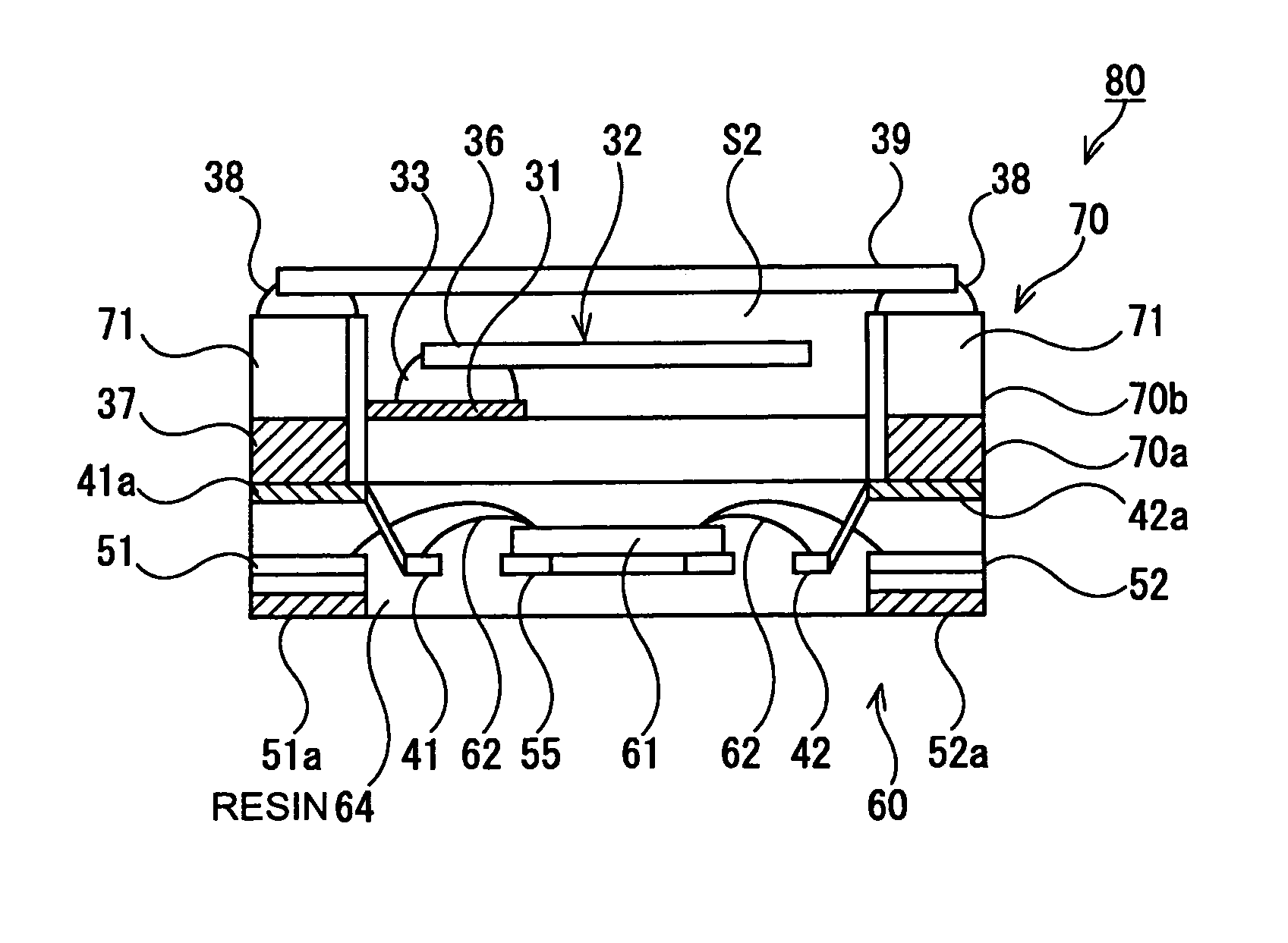
  • Piezoelectric oscillator, portable phone employing piezoelectric oscillator, and electronic apparatus employing piezoelectric oscillator
  • Piezoelectric oscillator, portable phone employing piezoelectric oscillator, and electronic apparatus employing piezoelectric oscillator
  • Piezoelectric oscillator, portable phone employing piezoelectric oscillator, and electronic apparatus employing piezoelectric oscillator

Examples


Embodiment Construction

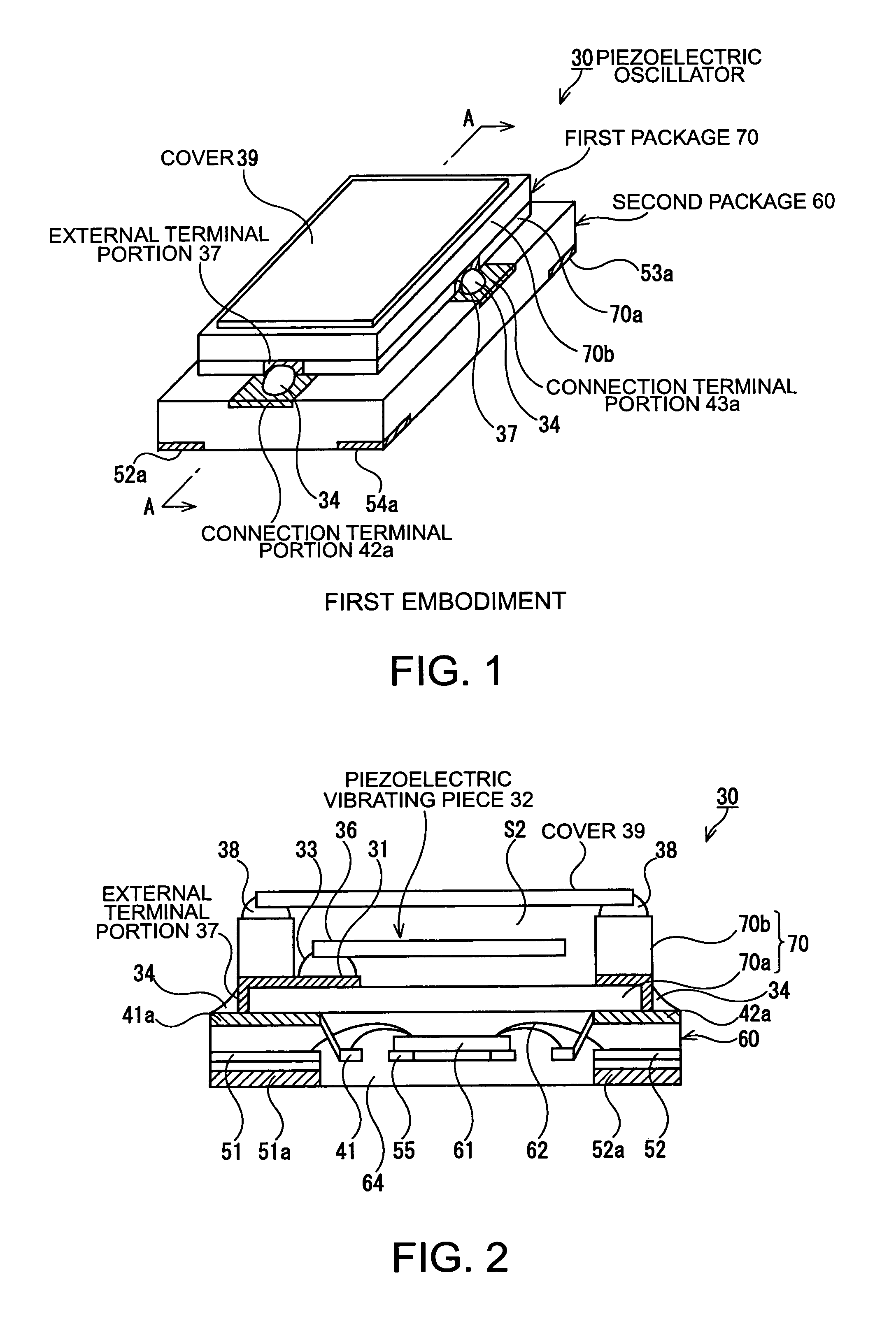
[0076]FIGS. 1 and 2 illustrate a first exemplary embodiment of a piezoelectric oscillator according to the present invention, wherein FIG. 1 is a schematic perspective view thereof, and FIG. 2 is a schematic cross-sectional view taken along the plane A—A of FIG. 1.

[0077]In the figures, the piezoelectric oscillator 30 includes a second package 60 housing an oscillating circuit element to be described later and a first package 70 being superposed on and fixed to the second package 60 and housing a piezoelectric resonator element 32 therein.

[0078]First, a structure of the first package 70 will be described.

[0079]The first package 70, as shown in FIG. 2, is formed by laminating and sintering a plurality of substrates 70a and 70b formed by shaping a ceramic green sheet including, for example, aluminum oxide as an insulating material in a rectangular shape. The substrate 70b is formed in a rectangular box shape, of which an upper end is opened, by forming a predetermined hole therein to h...


PUM


Abstract

To provide a piezoelectric oscillator in which, even after a first package and a second package are bonded to each other, the connection state can be easily observed externally, so that testability can be enhanced, and connection failure can be easily found out to perform a repair. A piezoelectric oscillator includes a first package housing a piezoelectric resonator element therein and having external terminal portions connected to excitation electrodes of the piezoelectric resonator element, and a second package housing an oscillating circuit element, the first package being superposed on and fixed to the second package. Herein, in the second package, the oscillating circuit element, which is connected to a lead frame, is molded out of resin, and connection terminal portions and mounting terminals formed of the lead frame are exposed at the second package. Furthermore, the external terminal portions of the first package are exposed at the side surfaces of the first package, and the external terminal portions and the connection terminal portions of the second package are electrically connected to each other by a conductive material.

Description

BACKGROUND OF THE INVENTION[0001]1. Field of Invention[0002]The present invention relates to a piezoelectric oscillator including a piezoelectric resonator element and an oscillating circuit element to oscillate the piezoelectric resonator element, and a portable phone and an electronic apparatus employing the piezoelectric oscillator.[0003]2. Description of Related Art[0004]Piezoelectric oscillators are widely used in packages of small-sized information apparatuses, such as HDDs (Hard Disk Drives), mobile computers, and IC cards, or mobile communication apparatuses, such as portable phones, car phones, and paging systems.[0005]A related art piezoelectric oscillator includes a piezoelectric vibrating unit having a piezoelectric resonator element and an oscillating circuit unit having an oscillating circuit element to oscillate the piezoelectric resonator element, and specifically a structure to house them in two different packages and fix the two packages.[0006]In the structure to f...

Claims


Application Information

Patent Timeline
Patent Type & Authority Patents(United States)
IPC IPC(8): H03B5/32H01L41/053H03H9/05H03H9/10
CPCH03H9/1021H03H9/0547H01L2924/181H01L2224/48091H01L2224/48227H01L2224/48247H01L2224/45144H01L2924/16195H01L2924/00012H01L2924/00014H01L2924/00H10N30/88
Inventor MIYAZAKI, KATSUHIKOKOYAMA, YUGOUNNO, YUKIHIRO
Owner SEIKO EPSON CORP
Learn More