Cache memory allocation method

a memory allocation and cache technology, applied in memory allocation/allocation/relocation, data processing applications, multi-programming arrangements, etc., can solve the problems of ineffective cache memory, adverse effect of cache memory operation taking, and ineffective cache memory

Inactive Publication Date: 2006-02-14
HITACHI LTD
View PDF9 Cites 64 Cited by
  • Summary
  • Abstract
  • Description
  • Claims
  • Application Information

AI Technical Summary

Benefits of technology

[0037]Although the invention described above is effective when being applied independently, the invention is more effective wh

Problems solved by technology

A cache memory configuration discussed above is the simplest, but it is not effective because a 12-bit tag must be stored simultaneously for storing a 1-byte (8 bits) instruction in this configuration.
Recently, it has been revealed that the cache memory, however, does not always function effectively in some case when the computer is used for multiprocessing.
Essentially, this has an adverse effect on the cache memory operation taking advantage of the localized servicing of programs.
To avoid thrashing, some measures for improvement have been proposed as will be described below, but any of these measures apparently have not produced a sufficient effect so far.
However, this forces the CPU to run other processes at low performance without the cache memory.
If, however, the number of processes is greater than the number of cache units, thrashing occurs as described above.
In recent personal co

Method used


Image

  • Cache memory allocation method
  • Cache memory allocation method
  • Cache memory allocation method

Examples


first embodiment

[0090]As the present invention, the “direct mapping” configuration of cache memory shown in FIG. 5 will first be discussed.

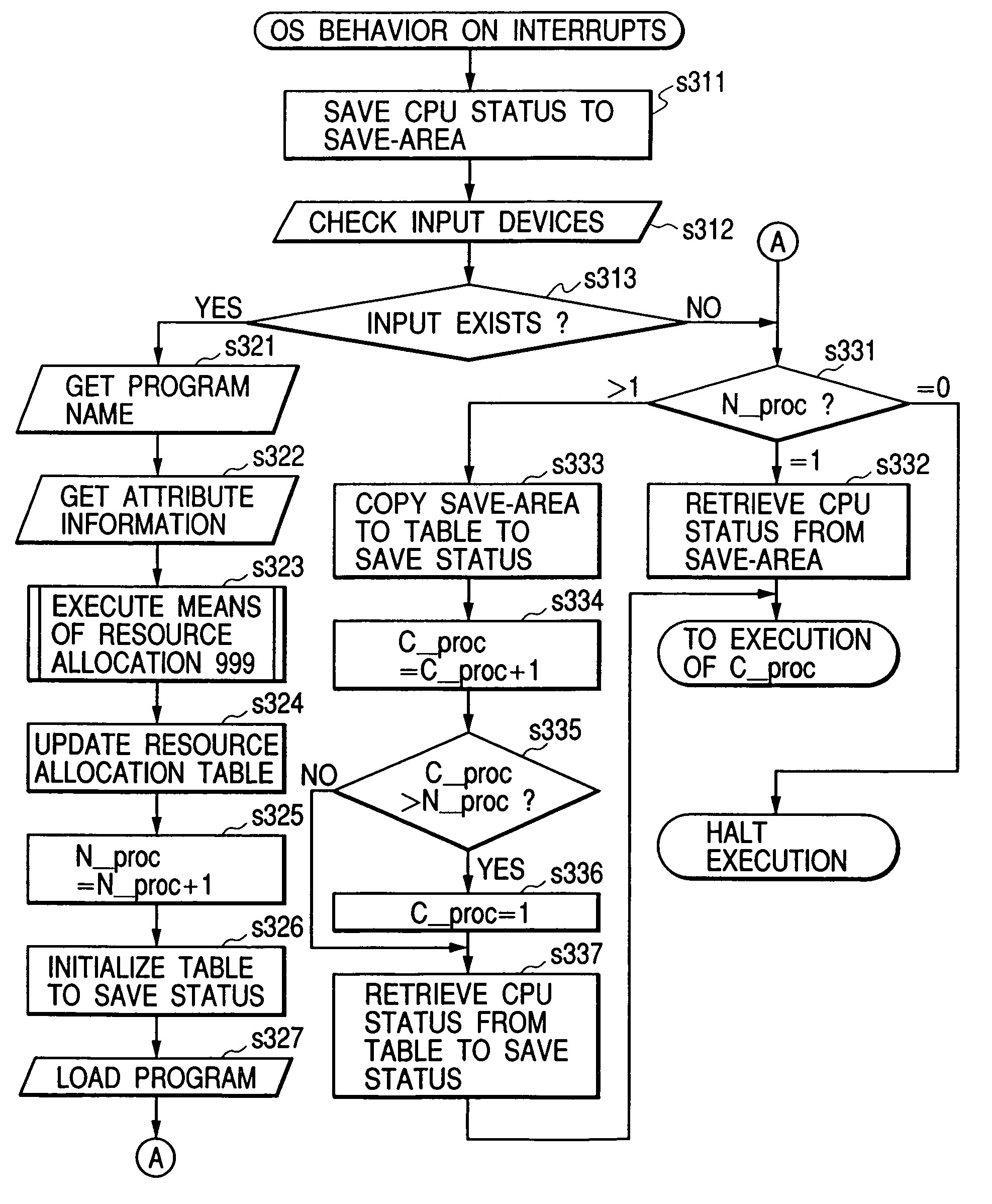
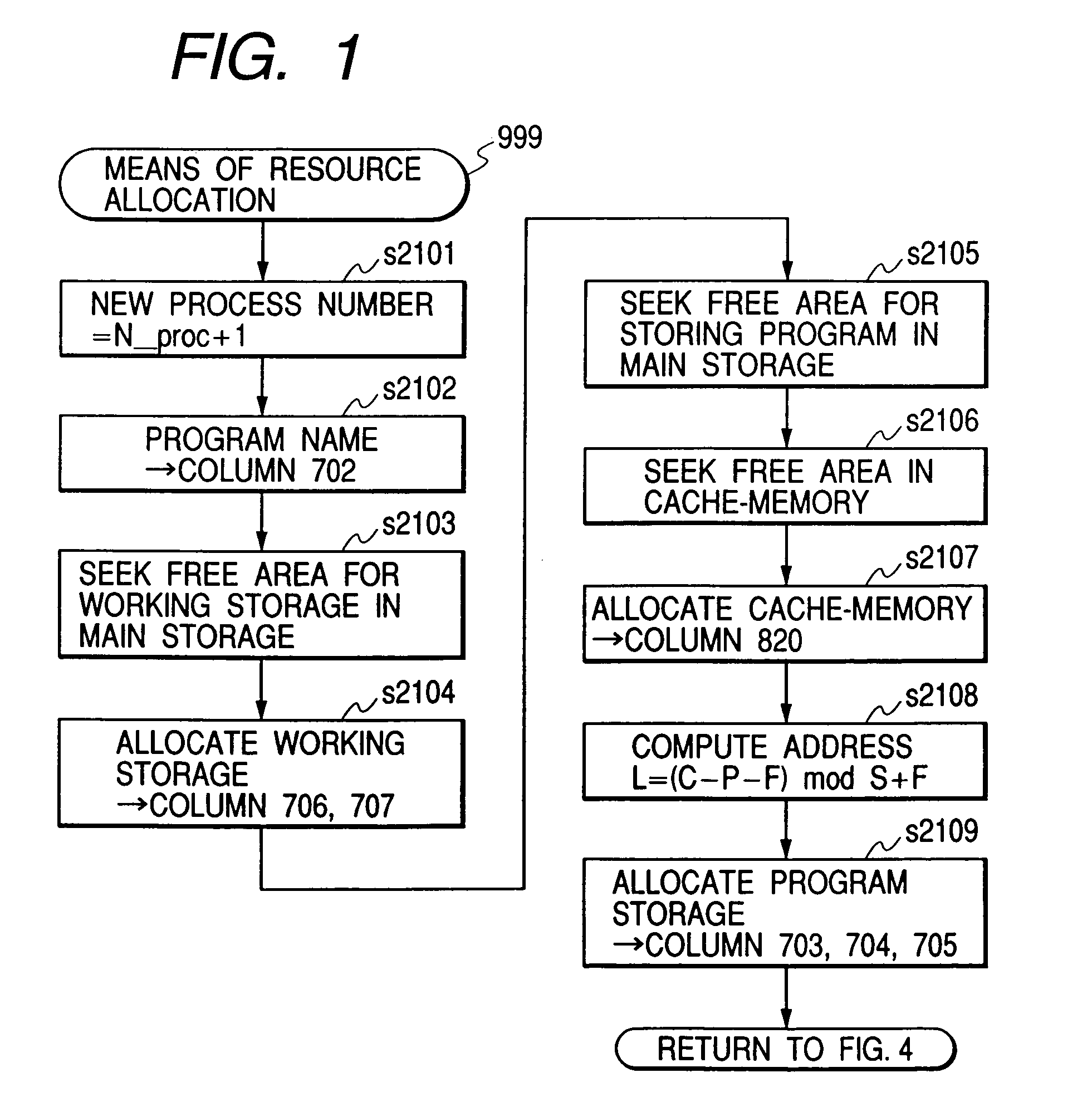
[0091]In this configuration, in order to prevent thrashing, it is advisable to position multiple concurrent processes on the main storage such that the principal parts of the processes do not use any same address on the cache memory. To do this, the following should be carried out: obtain the positions of the principal parts within the application programs from the attribute information 231, 232, and so on of the programs; determine the main storage addresses where the processes (programs) are to be loaded such that the corresponding cache addresses for storing the principal parts, which are determined by using the equation 1, differ from each other.

[0092]In this case, the required attribute information is provided in form shown in FIG. 11-a. That is, the attribute information 231 is recorded in this form, containing: program name 900, program size 901, entry ad...

second embodiment

[0107]Then, the present invention will be explained below with reference to hardware configuration shown in FIG. 6. FIG. 6 shows an example of cache memory configuration based on a scheme called an “application space sharing scheme,” which is a modification to the cache memory configuration shown in FIG. 5.

[0108]The components of the cache memory system in FIG. 6 and their operation are the same as those of the system in FIG. 5, but the difference between both lies in the way of generating an entry address. The system in FIG. 5 uses the 2nd to 12th bits of the value of the PC to generate an entry address, whereas the system in FIG. 6 uses the upper LL two bits (the 23rd and 24th bits) as is for the corresponding upper two bits of an entry address. Due to this, the bit positions from where the values are retrieved change, that is, the 11th to 22nd bits (12 bits in total) of the PC, are used, though the number of bits of the tag 112 is unchanged. In the second embodiment, entry addres...

third embodiment

[0133]Furthermore, the present invention will be explained below with reference to hardware configuration shown in FIG. 7. FIG. 7 shows an example of cache memory configuration based on a scheme called a “cache page register scheme,” which is a modification to the cache memory configuration shown in FIG. 5.

[0134]The components of the cache memory system in FIG. 7 and their operation are the same as those of the system in FIG. 5, but the difference between both lies in the way of generating an entry address. The system in FIG. 5 uses the 2nd to 12th bits of the value of the PC to generate an entry address, whereas the system in FIG. 7 is provided with a two-bit cache page register 160 and the contents of this register are used as upper two bits of an entry address. The contents of the cache page register are to be software updated by a suitable CPU instruction. Due to this, the tag 112 has additional two bits and the 11th to 24th bits of the PC (14 bits in total) are used.

[0135]In th...


PUM


Abstract

To assure the multiprocessing performance of CPU on a microprocessor, the invention provides a method of memory mapping for multiple concurrent processes, thus minimizing cache thrashing. An OS maintains a management (mapping) table for controlling the cache occupancy status. When a process is activated, the OS receives from the process the positional information for a specific part (principal part) to be executed most frequently in the process and coordinates addressing of a storage area where the process is loaded by referring to the management table, ensuring that the cache address assigned for the principal part of the process differs from that for any other existing process. Taking cache memory capacity, configuration scheme, and process execution priority into account when executing the above coordination, a computer system is designed such that a highest priority process can have a first priority in using the cache.

Description

FIELD OF THE INVENTION[0001]The present invention relates to a method of allocating a cache memory included in a computer system, and moreover relates to an operating system having the capability of cache memory allocation and a computer system operating under the control of such operating system.BACKGROUND OF THE INVENTION[0002]With the advance of microprocessor hardware, it is now required that software operating on the hardware has more advanced capabilities correspondingly. As one of such capabilities, a “multiprocessing capability” for concurrent running of a plurality of software units on a single microprocessor unit is required even for small information processing devices such as personal computers.[0003]As software for implementing the above capability, an operating system (OS) is prepared to take a duty of putting multiple running processes in order: the OS loads multiple processes in position into storage space and runs them in turn in a time-sharing manner. One of the ro...

Claims


Application Information

Patent Timeline
IPC IPC(8): G06F12/00G06F9/46G06F12/08G06F12/12
CPCG06F12/084G06F12/0842G06F12/126Y10S707/99956G06F2212/6042Y10S707/99953
Inventor AISAKA, KAZUOTOYAMA, KEISUKE
Owner HITACHI LTD
Why Eureka
Try Eureka