Ignition timing control system for light duty combustion engines

a control system and combustion engine technology, applied in the direction of ignition safety means, machines/engines, process and machine control, etc., can solve the problems of small low cost, light-duty combustion engines, and complex electronic control systems, and achieve simple design, long and useful life in service, and improve operating performance and emissions.

Inactive Publication Date: 2006-02-21
WALBRO LLC
View PDF2 Cites 45 Cited by
  • Summary
  • Abstract
  • Description
  • Claims
  • Application Information

AI Technical Summary

Benefits of technology

[0013]Object, features, and advantages of this invention include providing an ignition timing and air-to-fuel ratio control system which improves the operating performa

Problems solved by technology

Thus, a single closed loop feedback routine for ignition timing may not be ideal across a wide spectrum of operational modes.
Large automotive vehicle engines often have complex electronic control systems with numerous sensors measuring engine parameters such as intake air temperature, engine temperature, mass air flow, exhaust emissions, and engine speed.
Smaller

Method used


Image

  • Ignition timing control system for light duty combustion engines
  • Ignition timing control system for light duty combustion engines
  • Ignition timing control system for light duty combustion engines

Examples


first embodiment

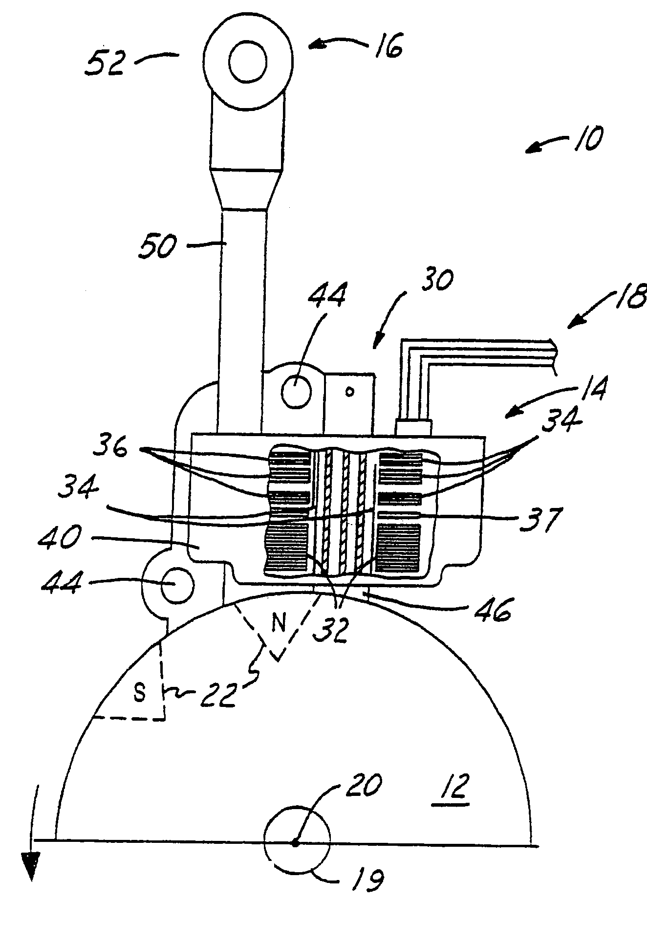
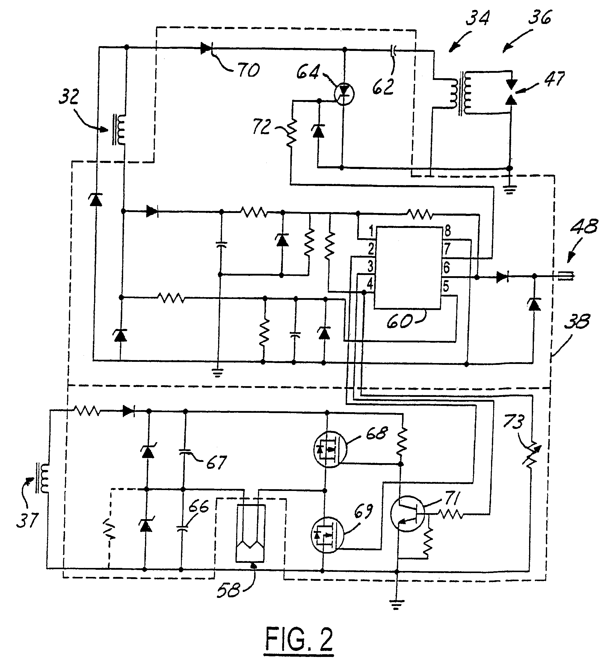
[0051]FIG. 7c shows an additional, optional section of the Warm Up sequence that may be added in order to take engine temperature into account when controlling the air-to-fuel ratio. This section begins with node D, which is preferably added to the Warm Up sequence between step 308 and the exit. Thus, this section would be executed once the Warm Up sequence is otherwise completed. Step 350 resets Solenoid RevCounter to 0, closes air bleed unit 90 such that the combustible mixture provided by the carburetor is enriched, and takes a sample of the current engine temperature. Referring briefly to FIG. 2, thermistor 73 is a heat dependent resistor connected to pin 4 of microcontroller 60. The thermistor and a standard resistor, also connected to pin 4, act as a voltage divider such that the signal on pin 4 is representative of the temperature dependent resistance of the thermistor, and hence the engine temperature. That temperature signal is used in step 352 of FIG. 7c to determine wheth...

second embodiment

[0052]FIG. 7d shows an additional, optional sequence that may be added to the Warm Up sequence in order to take engine temperature into account when controlling the air-to-fuel ratio. This section begins with node F, which is preferably added to the beginning of the Warm Up sequence before step 300, and is capable of distinguishing between cold and hot starts. By the time the sequence of FIG. 7d is executed, the system normally will have already cycled through the Cranking Sequence of FIG. 6. Step 370 waits four engine revolutions and then senses the engine temperature in a manner similar to steps 350 and 362, as previously explained. With the engine temperature sensed, step 372 compares the sensed temperature to a predetermined temperature, such as 50° F. If the sensed temperature is less than the predetermined temperature, thus indicating a cold start, then step 373 sends a “closed” Air / Fuel signal to solenoid 58. This causes the solenoid to remain closed, thus enriching the combu...


PUM


Abstract

A control system for a low cost, light duty combustion engine, where the control system generally utilizes engine speed and/or temperature input signals and independent operating sequences to determine a desired ignition timing and air-to-fuel ratio for a combustible mixture. There are several independent operating sequences, each one of which is designed to optimally control the engine under certain conditions. These operating sequences include a Cranking sequence that commences after the engine is initially turned on, a Warm Up sequence which follows the Cranking sequence, a Normal Mode sequence for typical operating conditions, an Acceleration sequence for certain increases in engine speed, a Come Down sequence for when a sufficient engine speed is followed by a certain decrease in speed, and a Recovery Bump sequence for when the engine speed dips below a predetermined level.

Description

REFERENCE TO RELATED APPLICATION[0001]This application is a continuation-in-part of U.S. application Ser. No. 10 / 186,522, filed Jul. 1, 2002 now Abandoned, both of which claim the benefit of provisional application, Ser. No. 60 / 306,381, filed Jul. 18, 2001.FIELD OF THE INVENTION[0002]The present invention relates generally to an ignition timing and air-to-fuel ratio control system for a low cost, light duty combustion engine. More specifically, the present invention relates to a system that controls the spark advance or retard, and the air-to-fuel ratio of a combustible mixture based upon an independent operating sequence selected according to the speed of the engine.BACKGROUND OF THE INVENTION[0003]Various independent electronic ignition timing control systems and electronic air-to-fuel ratio control systems are known and used in the art.[0004]Ignition timing, also referred to as spark timing, is an important aspect in the performance of internal combustion engines and has been wid...

Claims


Application Information

Patent Timeline
IPC IPC(8): F02P5/00F02D35/00F02D37/02F02D41/04F02D41/06F02D41/10F02D41/12F02D41/20F02D41/24F02D43/00F02D45/00F02P1/08F02P5/04F02P5/15
CPCF02D35/0061F02D37/02F02P5/045F02P5/1504F02P1/086F02D41/2422F02D2400/06Y02T10/46F02P5/1506F02P11/025Y02T10/40
Inventor ANDERSSON, MARTIN N.BORN, KEVIN P.PATTULLO, GEORGE M.ZBYTOWSKI, ERIC G.
Owner WALBRO LLC
Why Eureka
Try Eureka