
Power output apparatus and hybrid vehicle with power output apparatus mounted thereon

Inactive Publication Date: 2006-02-21
TOYOTA JIDOSHA KK
View PDF31 Cites 25 Cited by
  • Summary
  • Abstract
  • Description
  • Claims
  • Application Information

AI Technical Summary

Benefits of technology

[0008]The power output apparatus of the invention aims to actuate lubricating oil supply means, which is driven with power from an output shaft of an internal combustion engine, and ensure a required supply of lubricating oil, even while the internal combustion engine is at a stop. The power output apparatus of the invention also aims at smooth lubrication of mechanical part. The hybrid vehicle of the invention aims to reduce the number of components and still improve the overall energy efficiency of the vehicle.

Problems solved by technology

In a hybrid vehicle with the power output apparatus including the oil pump attached to the output shaft of the internal combustion engine, however, a sufficient supply of lubricating oil to the planetary gear is not assured in an EV drive mode, where the hybrid vehicle runs with the power from the motor, while the internal combustion engine is at a stop.
In a hybrid vehicle with the power output apparatus including the oil pump attached to the drive shaft, on the other hand, a sufficient supply of lubricating oil to the planetary gear is not ensured in a stop-time charging mode, where a battery mounted on the hybrid vehicle is charged with power from the internal combustion engine, while the vehicle is at a stop.
Attachment of the multiple oil pumps, however, undesirably increases the number of components included in the vehicle and raises the total weight of the vehicle.
The electrically-driven oil pump thus lowers the overall energy efficiency of the vehicle, compared with the oil pump that actuates with the power from the output shaft of the internal combustion engine.

Method used


Image

  • Power output apparatus and hybrid vehicle with power output apparatus mounted thereon
  • Power output apparatus and hybrid vehicle with power output apparatus mounted thereon
  • Power output apparatus and hybrid vehicle with power output apparatus mounted thereon

Examples


Embodiment Construction

[0033]One mode of carrying out the invention is discussed below as a preferred embodiment.

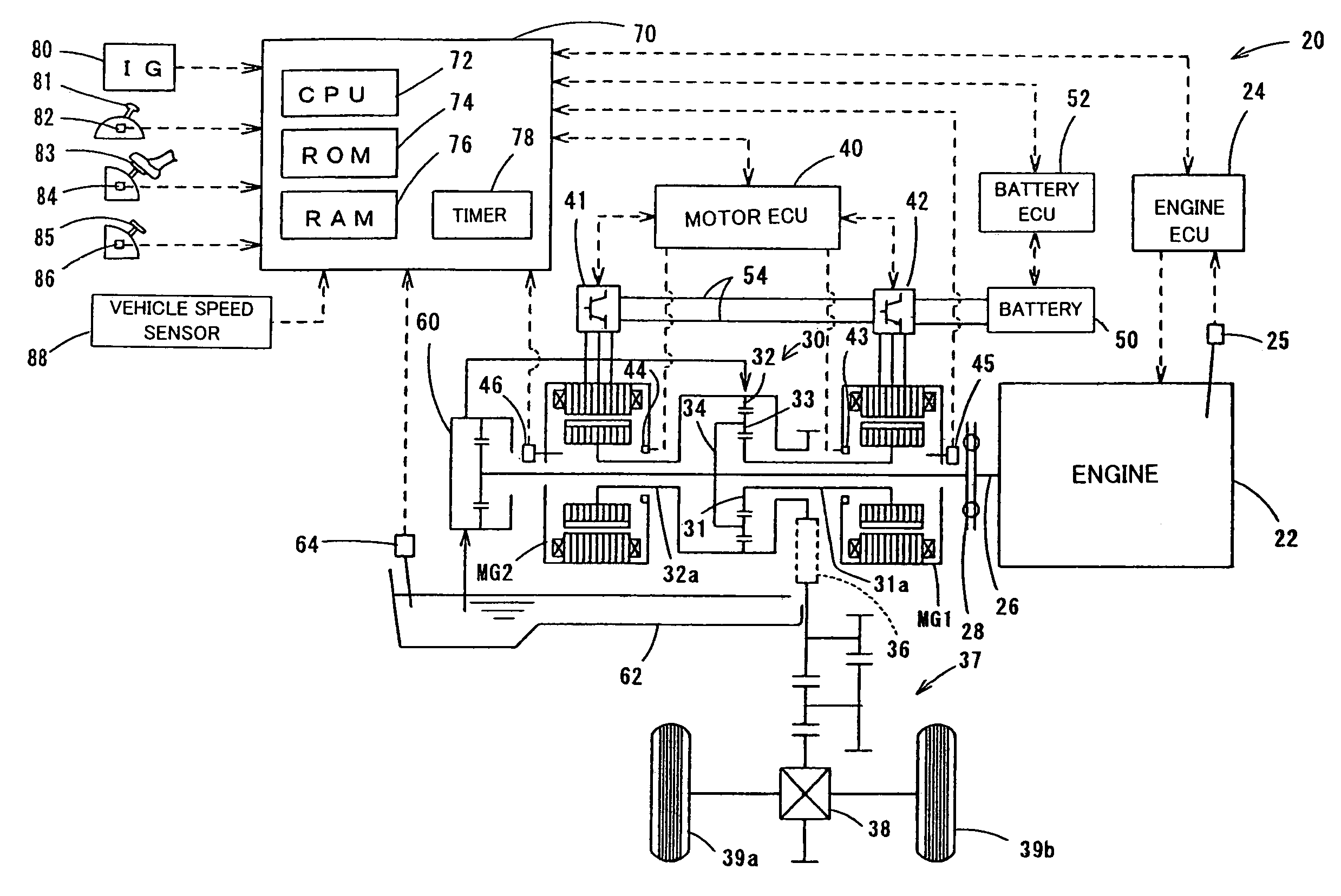
[0034]FIG. 1 schematically illustrates the construction of a hybrid vehicle 20 with a power output apparatus mounted thereon in one embodiment of the invention. The hybrid vehicle 20 of the embodiment includes an engine 22, a three-shaft-type power distribution integration mechanism 30 connecting with a crankshaft 26 or an output shaft of the engine 22 via a damper 28, a motor MG1 that is connected with the power distribution integration mechanism 30 and is capable of generating electric power, a MG2 that is also connected with the power distribution integration mechanism 30, an oil pump 60 that feeds a supply of lubricating oil to mechanical part including the power distribution integration mechanism 30, and a hybrid electronic control unit 70 that controls the whole power output apparatus.

[0035]The engine 22 is an internal combustion engine that utilizes a hydrocarbon fuel, such gas gasoline ...


PUM


Abstract

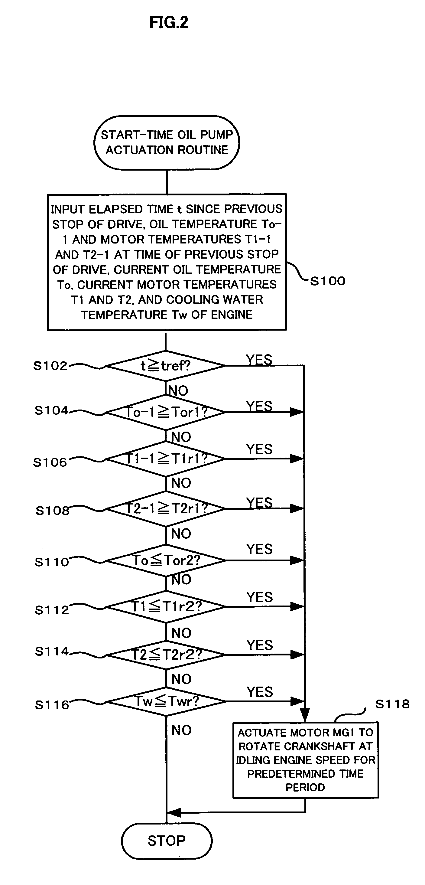
A hybrid vehicle may run with only the power from a motor MG2, while an engine is at a stop. In this state, the control procedure drives a motor MG1 to rotate a crankshaft at an idling engine speed for a predetermined time period, when at least one of an observed oil temperature in a sump, an observed temperature of the motor MG1, an observed temperature of the motor MG2, an observed revolving speed of the motor MG1, and an observed revolving speed of the motor MG2 is not less than a corresponding preset value. Rotation of the crankshaft at the idling engine speed results in driving an oil pump to feed a supply of lubricating oil to mechanical part of the power output apparatus including a power distribution integration mechanism.

Description

CROSS REFERENCE TO RELATED APPLICATION[0001]This is a continuation of Application PCT / JP02 / 08464, filed Aug. 22, 2002, now abandoned.BACKGROUND OF THE INVENTION[0002]1. Field of the Invention[0003]The present invention relates to a power output apparatus and a hybrid vehicle with a power output apparatus mounted thereon. More specifically the invention pertains to a power output apparatus that outputs power to a drive shaft, as well as to a hybrid vehicle with such a power output apparatus mounted thereon.[0004]2. Description of the Prior Art[0005]Various power output apparatuses mounted on a hybrid vehicle have been proposed, where an output shaft of an internal combustion engine and rotating shafts of two motors are connected with respective shafts of a planetary gear (for example, JAPANESE PATENT LAID-OPEN GAZETTE No. 9-56009). The power output apparatus has an oil pump that feeds a supply of lubricating oil to mechanical part including the planetary gear and is attached to the o...

Claims


Application Information

Patent Timeline
IPC IPC(8): B60K6/00B60K6/20B60K6/445B60L50/16B60W10/08B60W10/30B60W20/00F01M1/02F01M7/00F02D29/02F16H59/72F16H59/74F16H61/00
CPCB60K6/26B60W10/30F16H57/0434F16H61/0031B60K6/445Y02T10/6239B60L2240/425B60L2240/445B60L2240/485B60W20/00B60W2510/0676B60W2510/087B60W2510/107B60W2710/065F16H59/72F16H61/0021F16H61/0025F16H2059/746F16H2061/6607Y02T10/642F16H57/0473Y02T10/62Y02T10/64B60W2510/30B60W20/10B60W2710/30
Inventor ADACHI, MASATOSHIKOJIMA, MASAHIROKONDO, KOICHIHATA, HIROSHIOSHIMA, KEIJIRO
Owner TOYOTA JIDOSHA KK
Learn More