Illumination system and projection system adopting the same

a projection system and illumination system technology, applied in the field of illumination systems and projection systems, can solve the problems of inferior color purity, insufficient infrared and ultraviolet energy of lamps, and noise of fans, so as to achieve the effect of improving color purity and color gamu

Inactive Publication Date: 2006-02-21
SAMSUNG ELECTRONICS CO LTD
View PDF22 Cites 27 Cited by
  • Summary
  • Abstract
  • Description
  • Claims
  • Application Information

AI Technical Summary

Benefits of technology

[0009]Accordingly, it is an object of the present invention to provide an illumination system capable of forming a color image without a color wheel by using a light emitting device to emit a light beam having a predetermined wavelength so that color purity and color gamut is improved, and a projection system adopting the illumination system.

Problems solved by technology

These lamps emit too much unnecessary infrared and ultraviolet energy.
However, the cooling fan also acts as a noise source.
Also, since the spectrum of the lamp light source is widely distributed across many wavelengths, due to a narrow color gamut, the selection of color is limited, color purity is inferior, and the life span is short.
Thus, long-term use of the lamp is not possible.
Also, more light is lost at a boundary portion between neighboring color filters.
Furthermore, since the color wheel 105 rotates at a high speed, noise is generated.
Also, the mechanical movement of the driving motor has an adverse effect on stability.
Further, due to mechanical limitations of the driving motor, it is difficult to obtain a speed over certain ranges and a color breakup phenomenon occurs.
Also, since the price of the color wheel is very high, the manufacturing cost increases.

Method used


Image

  • Illumination system and projection system adopting the same
  • Illumination system and projection system adopting the same
  • Illumination system and projection system adopting the same

Examples


first embodiment

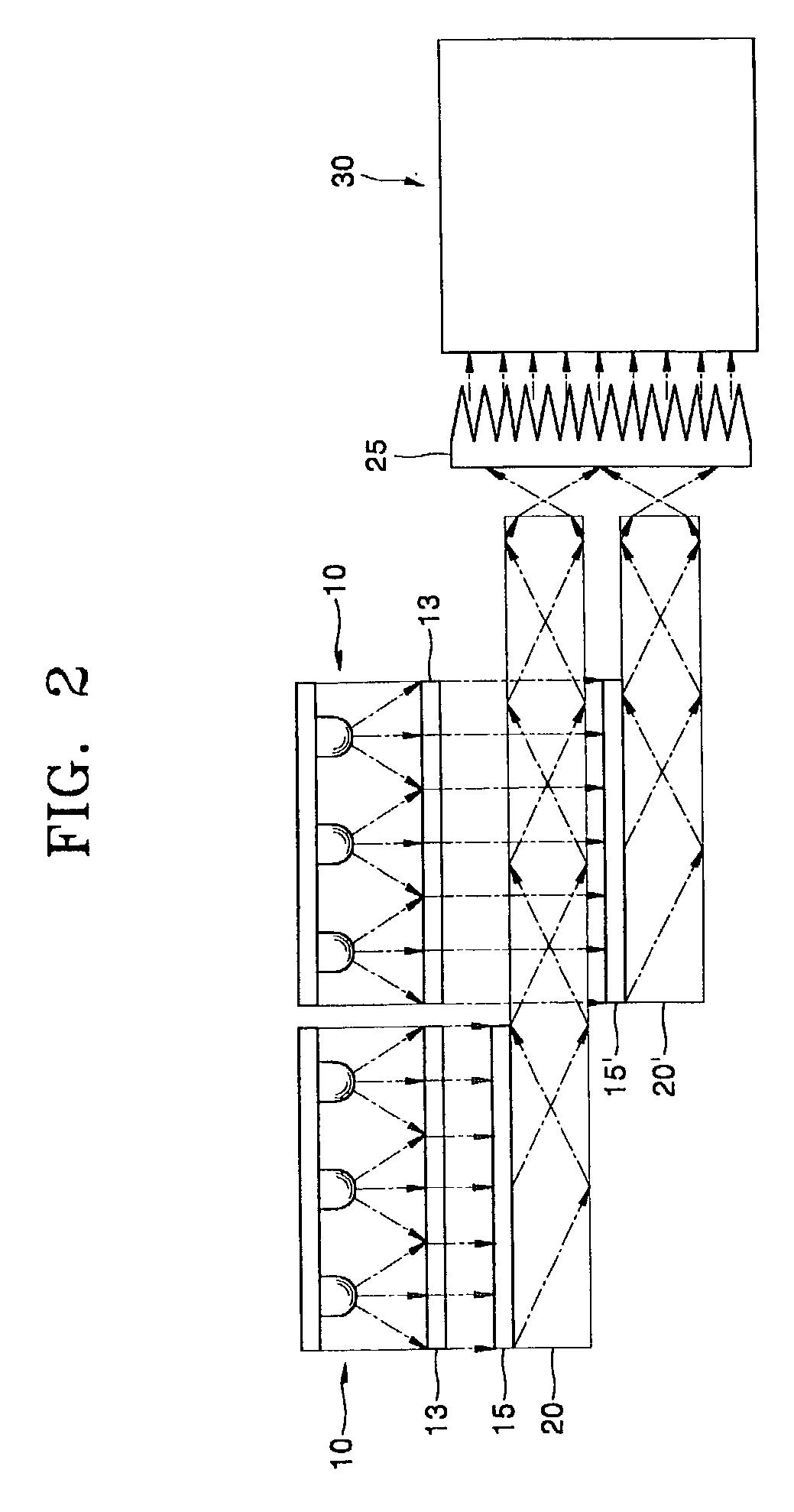
[0045]Referring to FIG. 2, an illumination system according to the present invention includes at least one light emitting device 10 to emit a light beam having a predetermined wavelength, a holographic optical element 15 to change a proceeding path of the light beam emitted from the light emitting device 10, and a waveguide 20 to guide the light beam passing through the holographic optical element 15.

[0046]An LED (light emitting diode), an LD (laser diode), an organic EL (electro luminescent), or an FED (field emission display) may be used as the light emitting device 10. Also, an array structure in which the light emitting devices 10 are arranged in a 2-dimensional array may be used. The light emitting device 10 or the light emitting device array can be formed to emit light beams having different wavelengths. For example, as shown in FIG. 4, the light emitting device 10 or the light emitting device array may include a first light emitting device 10a to emit a light beam having a re...

second embodiment

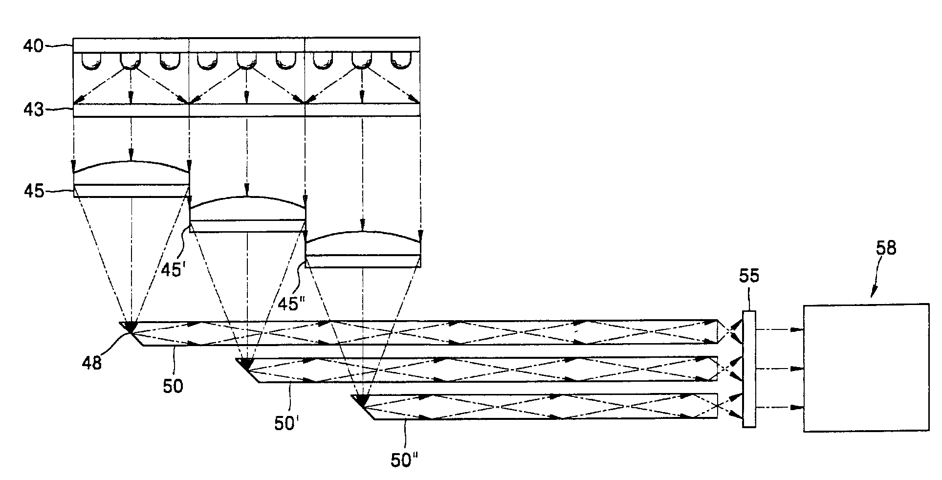
[0052]Referring to FIG. 5, an illumination system according to the present invention includes at least one light emitting device or light emitting device array 40, a waveguide 50 to guide a proceeding path of a light beam, and a focusing lens 45 to condense a light beam toward an input end portion of the waveguide 50. An LED (light emitting diode), an LD (laser diode), an organic EL (electro luminescent), or an FED (field emission display) can be used as the light emitting device or light emitting device array 40.

[0053]An input end portion of the waveguide 50 has a surface 48 inclined at a predetermined angle so that a light beam condensed by the focusing lens 45 is totally reflected in the waveguide 50. As an example, the surface 48 may be inclined at about 45°. Here, since the light beam is condensed at a point of the input end portion of the waveguide 50 by the focusing lens 45, the cross section of the light beam passing through the waveguide 50 can be further reduced.

[0054]Also...

third embodiment

[0067]the present invention, as shown in FIG. 9, includes fourth, fifth and sixth light emitting devices or light emitting device arrays 65, 66, and 67 to emit the R, G, and B color light beams, a parallel beam forming unit 70 to make parallel the light beams emitted from the fourth, fifth and sixth light emitting devices or light emitting device arrays 65, 66, and 67, fourth through sixth holographic optical elements 75, 76 and 77 to change the optical path of each of the R, G, and B color light beams at a predetermined angle, a waveguide 80 to totally reflect and pass the incident light beam passing through the holographic optical elements 75, 76, and 77, and a prism array 85 provided at an exit end portion of the waveguide 80.

[0068]The parallel beam forming unit 70 may be a Fresnel lens array or a collimating lens array. The R, G, and B color light beams emitted from the parallel beam forming unit 70 to be parallel to one another are incident on the waveguide 80 to be totally ref...


PUM


Abstract

An illumination system includes at least one light emitting device to emit a light beam having different wavelengths, a focusing lens to condense the light beam emitted from the light emitting device, and a waveguide having an incident surface inclined at a predetermined angle upon which the light beam condensed by the focusing lens is incident. A projection system includes at least one light emitting device to emit a light beam having the different wavelengths, a focusing lens to condense the light beam emitted from the light emitting device, a waveguide having an incident surface inclined at a predetermined angle on which the light beam is condensed by the focusing lens, a display device to form an image by processing the light beam passing through the waveguide according to an input image signal, and a projection lens unit to magnify the image formed by the display device and to project the magnified image toward a screen.

Description

CROSS-REFERENCE TO RELATED APPLICATIONS[0001]This application claims the benefit of Korean Application No. 2001-68816, filed Nov. 6, 2001, in the Korean Intellectual Property Office, the disclosure of which is incorporated herein by reference.BACKGROUND OF THE INVENTION[0002]1. Field of the Invention[0003]The present invention relates to an illumination system and a projection system adopting the same, and more particularly, to an illumination system which can realize a color image without a color wheel, and a projection system adopting the same.[0004]2. Description of the Related Art[0005]Referring to FIG. 1, a conventional projection system includes a light source 100, a first relay lens 102 to condense the light beam emitted from the light source 100, a color wheel 105 to split light beams incident from the first relay lens 102 into R, G and B color light beams, a fly eye lens 107 to make the light beam passing through the color wheel 105 uniform, a second relay lens 110 to conde...

Claims


Application Information

Patent Timeline
Patent Type & Authority Patents(United States)
IPC IPC(8): G03B21/00G03B21/20G02B5/32G02B19/00G02B27/00G02B27/18G02B27/28G03B21/14
CPCG02B27/286G02B27/0944G02B27/0994G02B27/0905G02B6/4214G02B6/4215G03B21/14
Inventor KIM, SUNG-HASOKOLOV, KIRILL SERGEEVICH
Owner SAMSUNG ELECTRONICS CO LTD
Why Eureka
Try Eureka