
Transconductance/C complex band-pass filter

a complex band-pass filter and transconductance technology, applied in the field of complex filters, can solve the problems of difficult to maintain the desired characteristic or transfer function interfere with the processing of received signals, and fail to maintain the required level of attenuation of out-of-band signals on the part of the channel select filter

Active Publication Date: 2006-02-21
AVAGO TECH INT SALES PTE LTD
View PDF8 Cites 42 Cited by
  • Summary
  • Abstract
  • Description
  • Claims
  • Application Information

AI Technical Summary

Benefits of technology

[0015]A complex filter, such as the channel select filter of a radio transceiver, is implemented using a transconductance/C topology that permits tuning of the ratio of gm/C to ensure stability of the poles and zeros required by the filter to achieve its specified transfer fun...

Problems solved by technology

These include mirror image or sideband components, as well as distortion and intermodulation components, all of which can interfere with the processing of the received signals within the selected channel.
One of the difficulties presented by the integration of radio transceivers on monolithic integrated circuits is that it is difficult to steadily maintain the desired characteristic or transfer function of the channel select filter over the variations in circuit characteristics that result from variations in processing different batches of the integrated circuits, as well as those changes in circuit characteristics due to variations in the ambient temperature and supply voltage.
Variations in these parameters can lead to the failure on the part of the channel select filter to maintain the required level of attenuation of the out-of-band signals to the levels specified for the particular design.

Method used


Image

  • Transconductance/C complex band-pass filter
  • Transconductance/C complex band-pass filter
  • Transconductance/C complex band-pass filter

Examples


Embodiment Construction

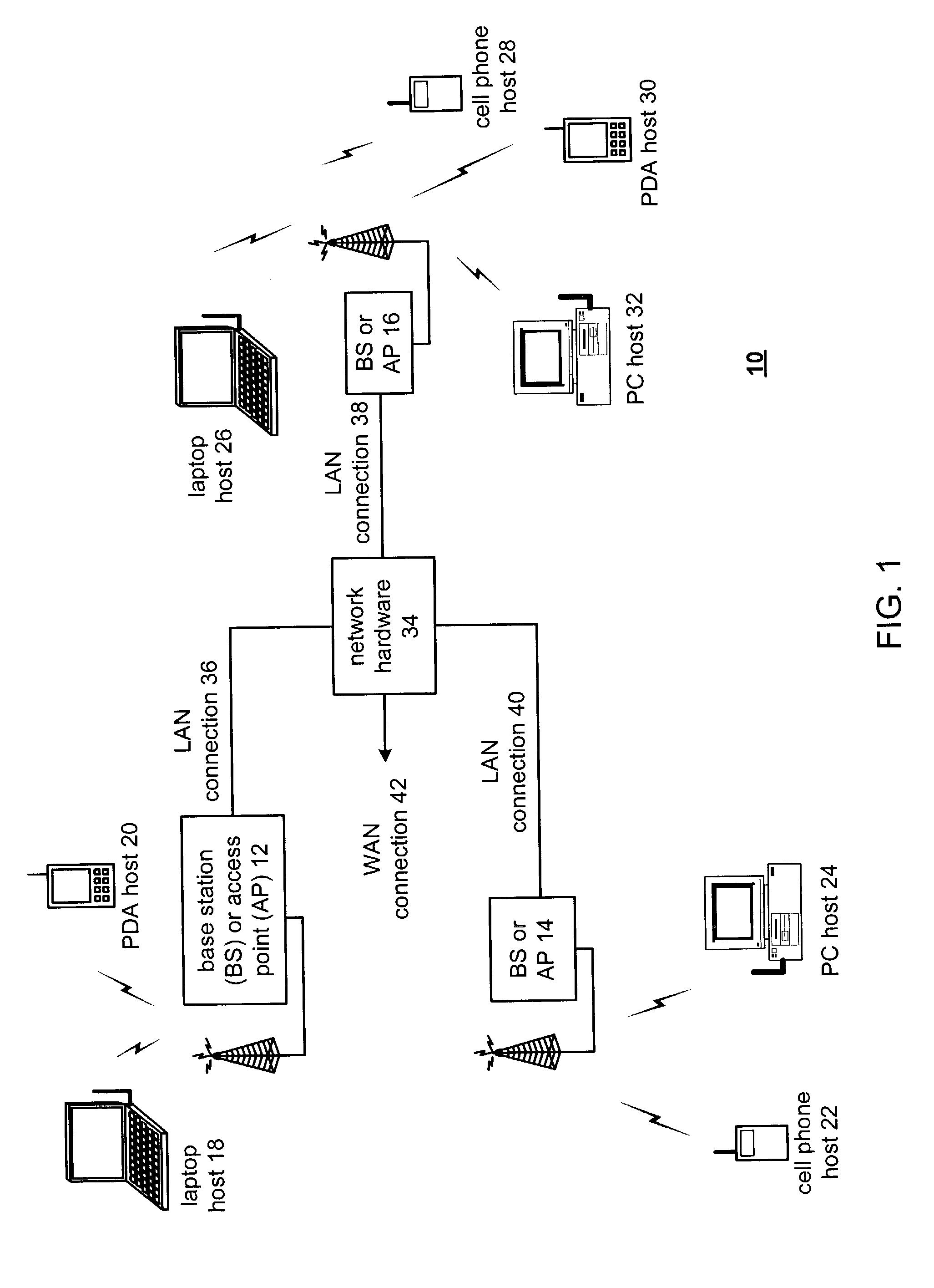
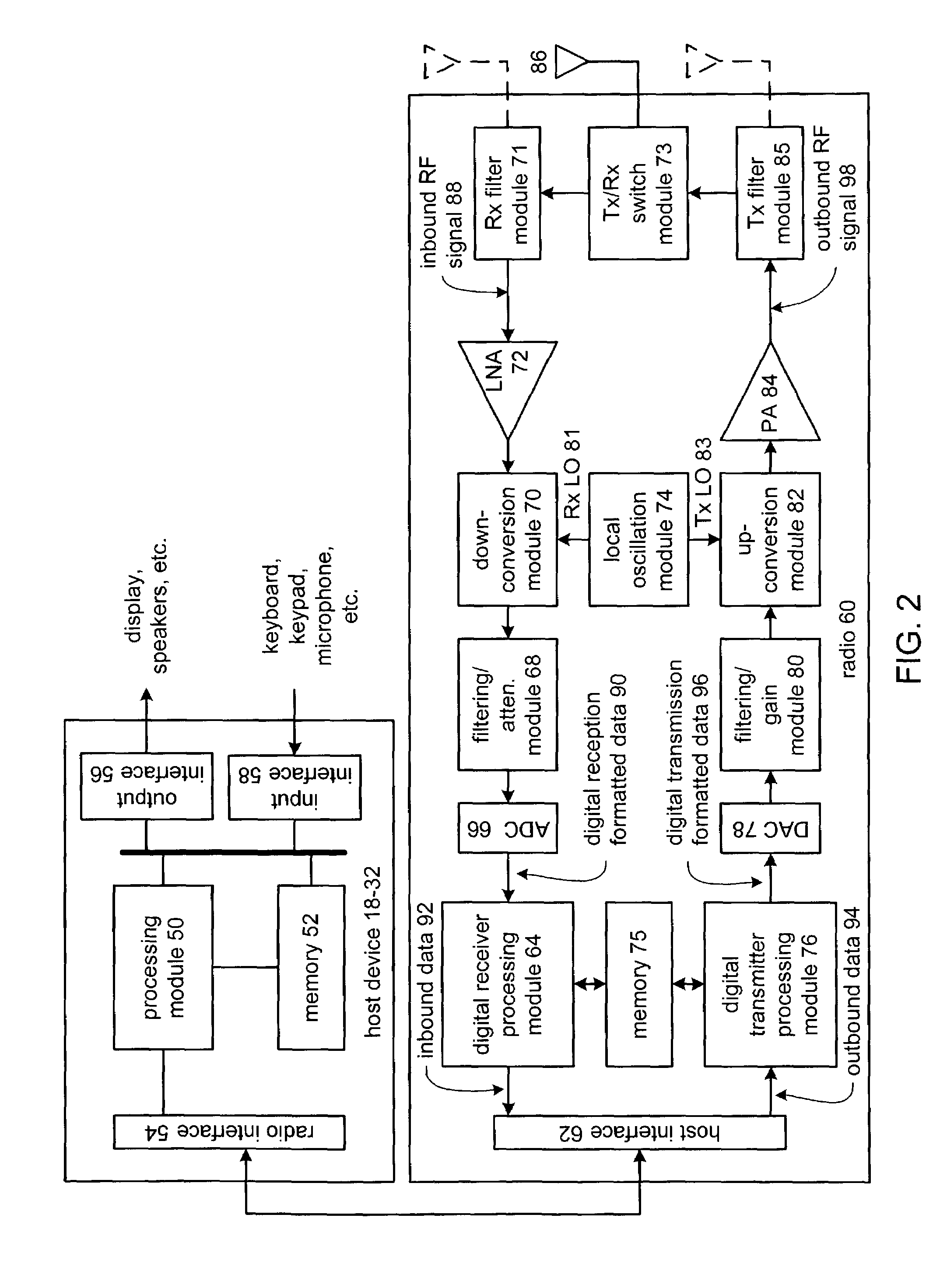
[0036]FIG. 1 is a schematic block diagram illustrating a communication system 10 that includes a plurality of base stations and / or access points 12–16, a plurality of wireless communication devices 18–32 and a network hardware component 34. The wireless communication devices 18–32 may be laptop host computers 18 and 26, personal digital assistant hosts 20 and 30, personal computer hosts 24 and 32 and / or cellular telephone hosts 22 and 28. The details of the wireless communication devices will be described in greater detail with reference to FIG. 2.

[0037]The base stations or access points 12–16 are operably coupled to the network hardware 34 via local area network connections 36, 38 and 40. The network hardware 34, which may be a router, switch, bridge, modem, system controller, et cetera, provides a wide area network connection 42 for the communication system 10. Each of the base stations or access points 12–16 has an associated antenna or antenna array to communicate with the wirel...


PUM


Abstract

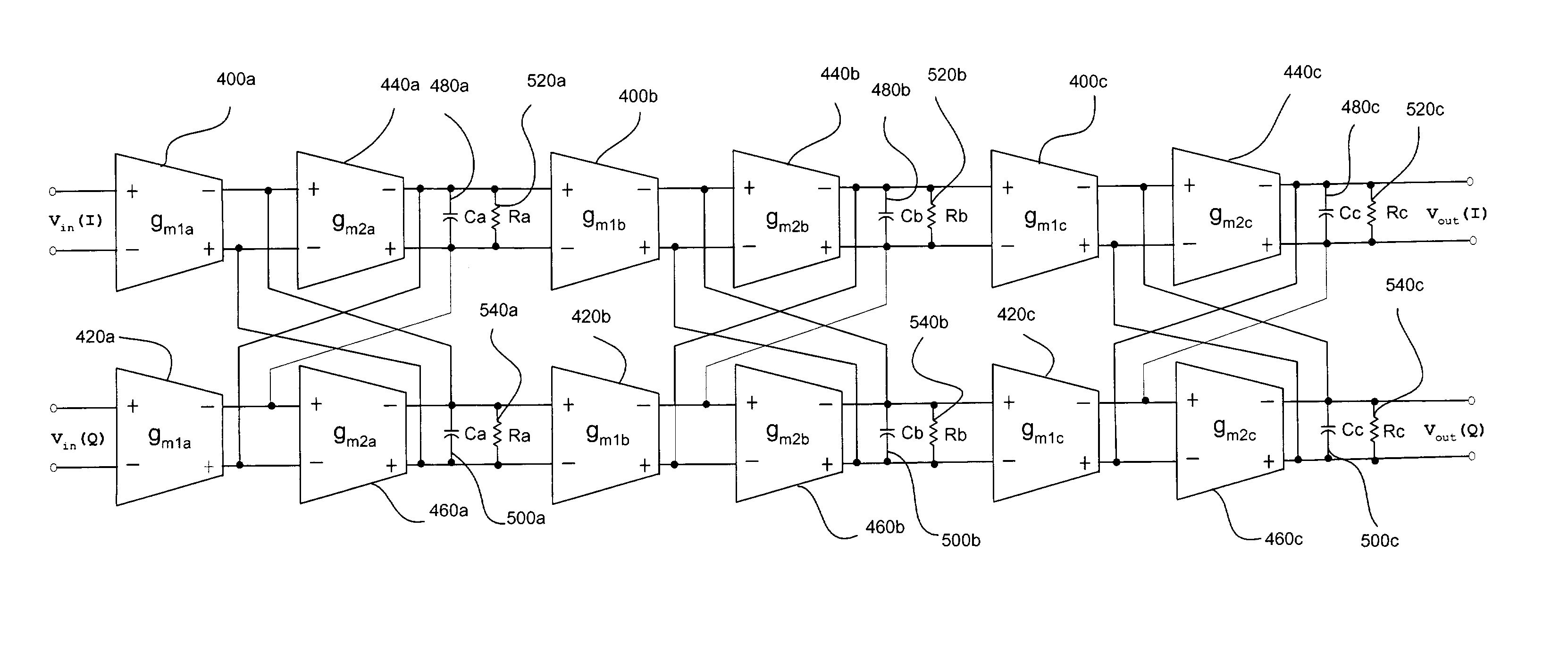
A complex filter such as the channel select filter in a radio transceiver is implemented using a transconductance / C topology to benefit from the ability to tune such filters and thereby stabilize the output transfer function of the filter over variations in temperature, power supply voltage and process. The topology is based on an active R / C biquadratic topology to achieve the additional benefit of independently controlled stages. The problem created by the R in the output impedance is can be overcome by separately tuning the R value along with the transconductance / C ratio, by implementing the R as a transconductance amplifier having common mode feedback, or by implementing the transconductance amplifiers of the topology using Nauta transconductors, and unbalancing the common mode circuit of the Nauta transconductor to achieve a differential resistance that can be used to implement the R in the output impedance.

Description

CROSS REFERENCE TO RELATED APPLICATIONS[0001]This application is a continuation-in-part of and incorporates by reference application Ser. No. 10 / 244,102, filed on Sep. 13, 2002, said filed application having the same named inventor as the present application.BACKGROUND[0002]1. Field of the Invention[0003]This invention relates to complex filters, and more particularly to a complex filter topology that is based on a biquadratic topology but provides a tunable filter characteristic that is a function of transconductance and capacitance.[0004]2. Description of the Related Art[0005]Communication systems are known to support wireless and wire lined communications between wireless and / or wire lined communication devices. Such communication systems range from national and / or international cellular telephone systems to the Internet to point-to-point in-home wireless networks. Each type of communication system is constructed, and hence operates, in accordance with one or more communication s...

Claims


Application Information

Patent Timeline
IPC IPC(8): H04B1/10H04B7/00H03H11/04H03H11/22
CPCH03H11/04H03H11/22H03L7/08H03L7/0805H03H11/0422H03L2207/06H03H2011/0494H03H11/08
Inventor MARHOLEV, BOJKO F.
Owner AVAGO TECH INT SALES PTE LTD
Learn More