Welding method, welding device, welded joint, and welded structure

a welding device and welding technology, applied in the direction of welding/cutting media/materials, welding apparatus, manufacturing tools, etc., can solve the problems of difficult tracing of weld lines, conventional arc sensing methods, and difficulty in tracing weld lines, so as to accurately force out melt and improve welding workability.

Inactive Publication Date: 2006-02-28
NIHON KENKI CO LTD
View PDF10 Cites 18 Cited by
  • Summary
  • Abstract
  • Description
  • Claims
  • Application Information

AI Technical Summary

Benefits of technology

[0044]According to the twenty-first or twenty-second aspect, even if a movement or distortion takes place in the groove in the direction of the width of the groove due to restraint conditions for the first base material and the second base material and/or a thermal distortion or the like during welding, the welding can be appropriately corrected to trace a weld line in the groove by moving the position of the tip of the welding wire closer or away on the basis of the actual average vo

Problems solved by technology

Depending on the shape of a welded joint structure or welded structure, however, it may be difficult, from the standpoint of actually performing welding, to arrange a bead beforehand on the back side of a groove as in the above-mentioned conventional technique.
Conventional arc sensing methods, however, have difficulty in tracing a weld line because they are not designed to be applicable to such a welding

Method used


Image

  • Welding method, welding device, welded joint, and welded structure
  • Welding method, welding device, welded joint, and welded structure
  • Welding method, welding device, welded joint, and welded structure

Examples


first embodiment

1. First Embodiment

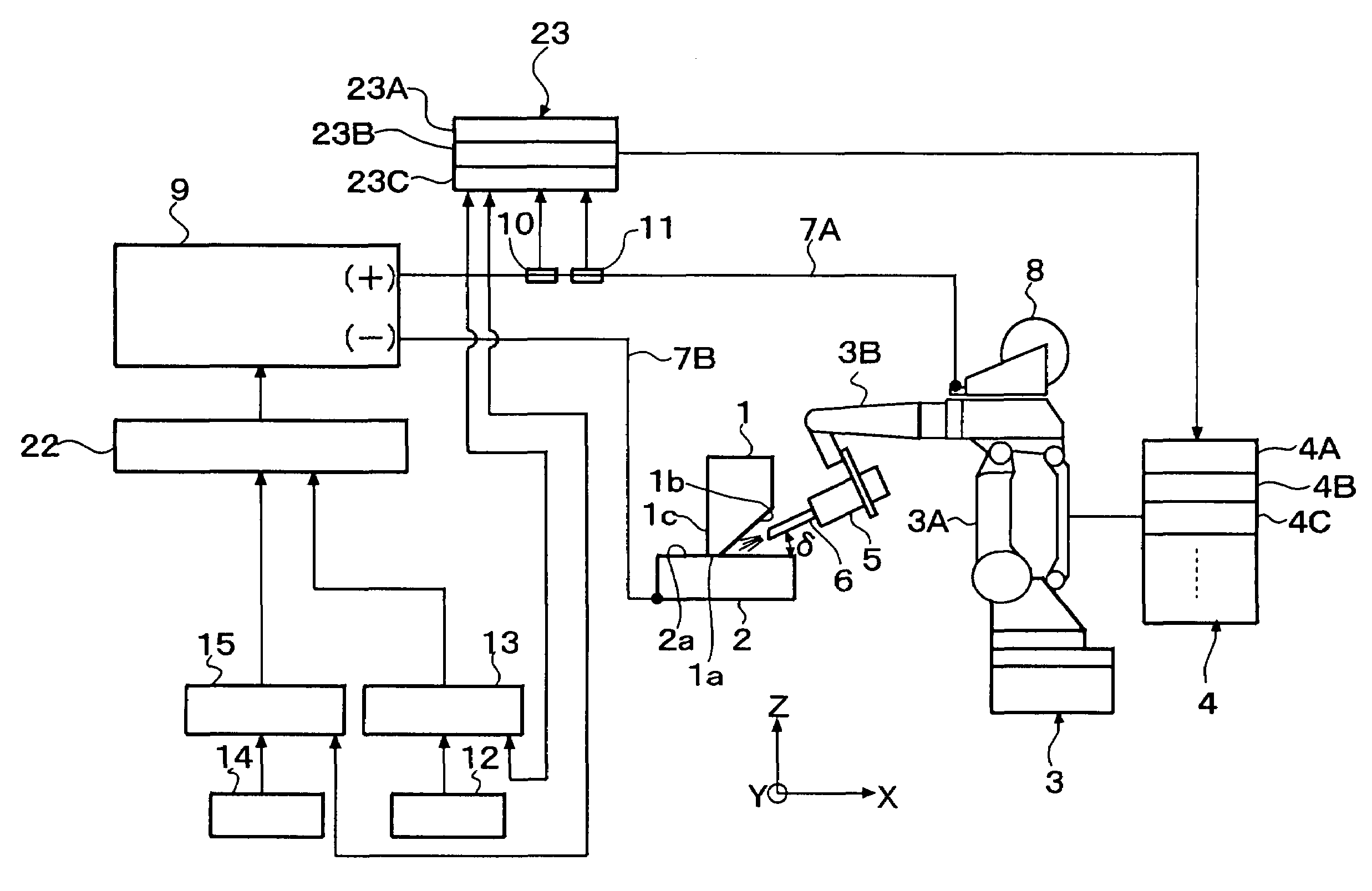
[0070]FIG. 1 through FIG. 9 are drawings for illustrating a welding method according to a first embodiment of the present invention.

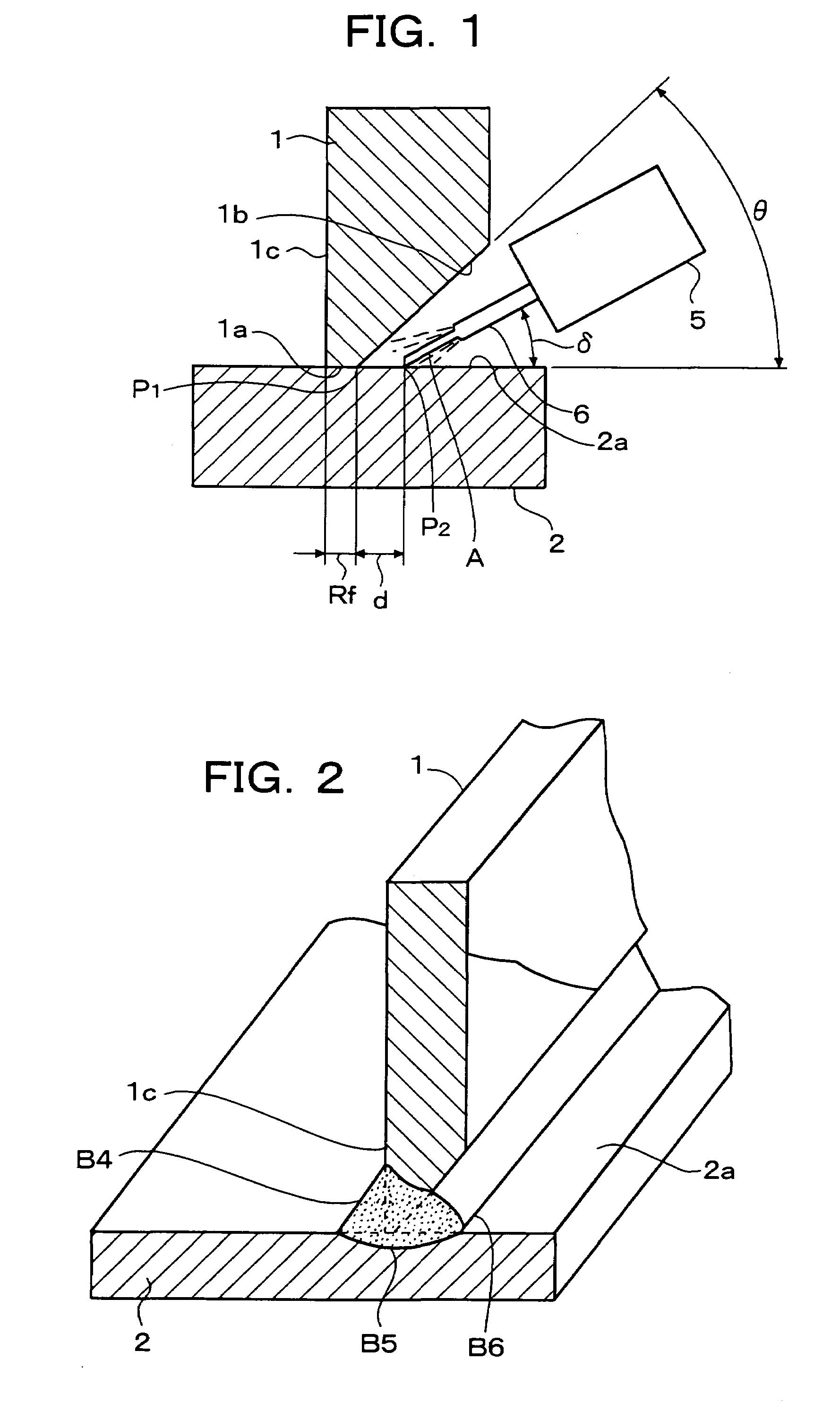
[0071]FIG. 1 is a schematic view illustrating welding work for a “T” joint by the first embodiment of the welding method of the present invention, and FIG. 2 is a perspective view showing the “T” joint welded by the welding work illustrated in FIG. 1.

[0072]FIG. 1 illustrates a state upon welding a first base material 1 and a second base material 2 with each other by bringing them into abutment in the form of “T”. The first base material 1 is provided at a butted end portion thereof with a root face 1a and a single groove face 1b which serves to form a single bevel groove. The second base material 2 has a flat surface 2a positioned in contact with the root face 1a of the first base material 1, and in combination with the first base material 1, forms a “T” joint. Numeral 5 designates a welding torch, and numeral 6 indicates a welding wi...

second embodiment

2. Second Embodiment

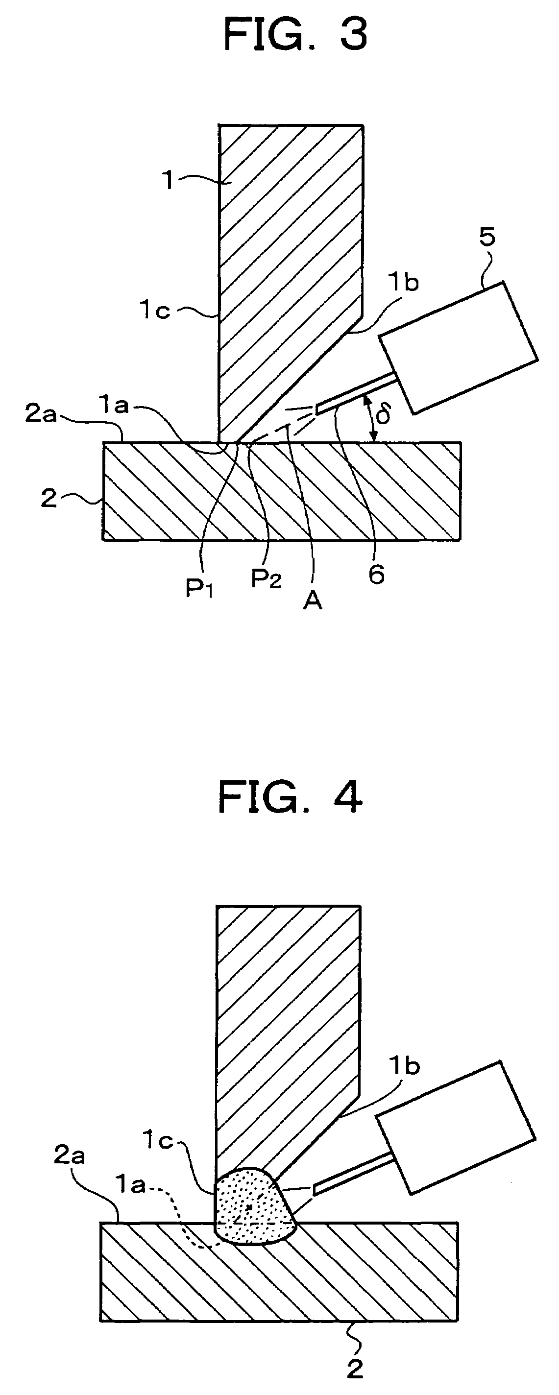
[0103]FIG. 10 is a schematic view illustrating a second embodiment of the welding method according to the present invention, and shows welding work for a “T” joint. In this embodiment, elements equivalent to the corresponding elements in the above-described first embodiment are designated by like reference signs, and overlapping descriptions are omitted.

[0104]In this second embodiment, a welding wire 6 held in place on a welding torch 5 and fed by unillustrated feeding means is held at an inclination a relative to a flat surface 2a of a second base material 2 while being directed to an aimed point P2. In this embodiment, welding is performed while causing the welding wire 6 to weave. The weaving is effected by driving the welding torch 5 under control such that the welding wire 6 oscillates at a predetermined amplitude in the direction of an arrow 50 while maintaining the above-described inclination ä. The amplitude and pitch of oscillation for the weaving are de...

third embodiment

3. Third Embodiment

[0107]FIG. 11 is a schematic view illustrating a third embodiment of the welding method according to the present invention, and shows welding work for a “T” joint. In this embodiment, elements equivalent to the corresponding elements in the first and second embodiments are designated by like reference signs, and overlapping descriptions are omitted.

[0108]In the third embodiment, weaving of a welding wire 6 is performed by driving a welding torch 5 under control such that a tip of a welding wire 6 is swung in the form of a circular arc over á degrees about a predetermined inclination ä as a center. In this third embodiment, a bead B4 in the form of a fillet weld can also be deposited between a back side 1c of a first base material 1, said back side being located on the back side of the groove, and a flat surface 2a as in the above-mentioned embodiments.


PUM

PropertyMeasurementUnit
Timeaaaaaaaaaa
Currentaaaaaaaaaa
Electric potential / voltageaaaaaaaaaa

Abstract

A welding method is disclosed for butt welding a first base material 1 and a second base material 2 with each other. To also permit stable and efficient formation of a bead in the form of a fillet weld on a back side of a groove by conducting arc welding from the side of the groove without arranging a bead beforehand on the back side of the groove, the first member 1, on which a root face 1a and a single groove face 1b have been formed, is brought at its root face 1a into contact with a flat surface 2a of the second base material 2. A welding wire 6 is arranged facing on the groove formed by the contact between the first base material 1 and the second base material 2. The first base material 1 and the second material 2 are caused to fuse at an area of contact between them by an arc from the welding wire 6. A melt, which has been formed by the fusion at the area of contact and the like, is forced out to the back side of the groove to form a bead B4 in the form of a fillet weld on the back side of the groove.

Description

TECHNICAL FIELD[0001]This invention relates to a welding method to be conducted by arranging a single groove face, a welding apparatus useful in the welding method, and a welded joint and welded structure available by the method.BACKGROUND ART[0002]In a variety of welded structures such as steel skeleton constructions of buildings, bridges, industrial equipment and construction machinery, “T” joints are adopted as welded joints in many instances. In general, a “T” joint is formed by bringing a single groove face of one of members into abutment against a surface of the other member to arrange these members in a “T” pattern and forming a bead in a groove, which has been formed at an area of contact between the surface of the above-mentioned other member and the above-mentioned one member, to join these members together. As known examples of this type, there are the welding methods disclosed in JP-A-08332567 and JP-A-06023544. The former conventional technique requires advance arrangem...

Claims


Application Information

Patent Timeline
IPC IPC(8): B23K9/12B23K9/022B23K9/025B23K9/095B23K9/173B23K33/00
CPCB23K9/022B23K9/025B23K9/0256B23K33/004B23K9/126B23K9/1735B23K33/00B23K9/0953B23K9/173
Inventor TAKATANI, TORUTAKANO, YUTAKAMIYANAGI, NAOKIYAMAMOTO, HIKARUSAKURAI, SHIGEYUKIHIRAKAWA, MANABU
Owner NIHON KENKI CO LTD
Why Eureka
Try Eureka