Method for making high speed, high areal density inductive write structure

a write structure and data density technology, applied in the field of magnetic data recording, can solve the problems of limited b/sub>sat of materials and unsatisfactory domain formation in the poles, and achieve the effects of improving magnetic performance characteristics, high overwriting, and low non-linear transition shi

Inactive Publication Date: 2006-03-07
WESTERN DIGITAL TECH INC
View PDF8 Cites 153 Cited by
  • Summary
  • Abstract
  • Description
  • Claims
  • Application Information

AI Technical Summary

Benefits of technology

[0013]The present invention provides an inductive write element having improved magnetic performance characteristics, including high overwrite, low non-linear transition shift, high areal density and high data rate. The write element includes first and second poles, each constructed of a magnetic material and joined to one another to form a magnetic yoke. The poles are joined to one another at one end to form a back gap region, the other end having a write gap defined between the poles. An electrically conductive coil passes through the yoke between the first and second pole, and insulating material electrically isolates the electrically conductive coil from the magnetic yoke. The second pole includes a layer of a laminated high magnetic moment material, sputter deposited as a sheet film across the inner surface of the pole adjacent to the insulation material and write gap.

Problems solved by technology

However, high Fe content NiFe alloy has a high magnetostriction constant λs (on the order of 10−5) which causes undesirable domain formation in the poles.
However, such materials generally have limited Bsat.

Method used


Image

  • Method for making high speed, high areal density inductive write structure
  • Method for making high speed, high areal density inductive write structure
  • Method for making high speed, high areal density inductive write structure

Examples


Embodiment Construction

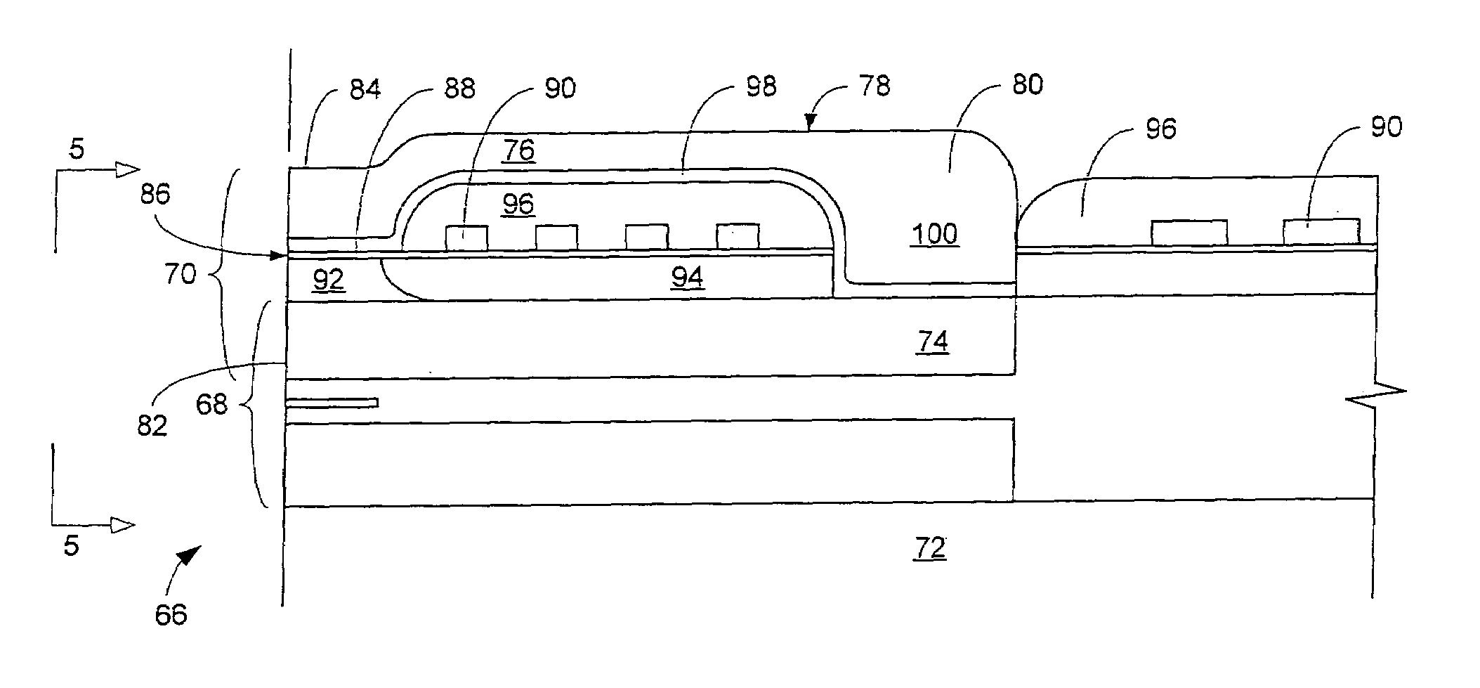
[0027]With reference to FIG. 3 the present invention is embodied in a merged read / write head 66 including a read element 68 and an integral write element 70, both of which are built upon a substrate 72. The read element 68 having been described with reference to the background of the invention, the present description will focus on the write element 70, which embodies the subject matter of the present invention.

[0028]The write element 70 includes first and second poles 74, 76, which together join to form a magnetic yoke 78. The poles 74, 76 join at one end to form a back-gap 80, and are separated from one another everywhere else. Opposite the back-gap, each pole 74, 76 terminates in a pole tip 82, 84. Opposite the back gap 80, the poles 74, 76 are separated by a write gap 88. A layer of dielectric write gap material 89 fills the write gap and extends beyond the write gap into the interior of the yoke 78. An electrically conductive coil 90 passes through the yoke 78 sitting atop the ...


PUM

PropertyMeasurementUnit
thicknessaaaaaaaaaa
writing currentaaaaaaaaaa
thickaaaaaaaaaa

Abstract

An inductive write element is disclosed for use in a magnetic data recording system. The write element provides increased data rate and data density capabilities through improved magnetic flux flow through the element. The write element includes a magnetic yoke constructed of first and second magnetic poles. The first pole includes a pedestal constructed of a high magnetic moment (high Bsat) material, which is preferably FeRhN nanocrystalline films with lamination layers of CoZrCr. The second pole includes a thin inner layer of high Bsat material (also preferably FeRhN nanocrystalline films with lamination layers of CoZrCr), the remainder being constructed of a magnetic material capable of being electroplated, such as a Ni—Fe alloy. An electrically conductive coil passes through the yoke between the first and second poles to induce a magnetic flux in the yoke when an electrical current is caused to flow through the coil. Magnetic flux in the yoke produces a fringing field at a write gap whereby a signal can be imparted onto a magnetic medium passing thereby.

Description

CROSS-REFERENCE TO RELATED APPLICATIONS[0001]This application is a Divisional of U.S. application Ser. No. 09 / 617,791, filed Jul. 18, 2000, now U.S. Pat. No. 6,618,223, Sep. 9, 2003, which is hereby incorporated by reference in its entirety.FIELD OF THE INVENTION[0002]The present invention relates to magnetic data recording and more specifically to a method for making a high data rate, high data density inductive writer.BACKGROUND OF TH INVENTION[0003]Magnetic disk drives are used to store and retrieve data for digital electronic apparatus such as computers. In FIGS. 1A and 1B, a magnetic disk data storage system 10 of the prior art includes a sealed enclosure 12, a disk drive motor 14, one or more magnetic disks 16, supported for rotation by a drive spindle 18 of motor 14, and an actuator 20 including at least one arm 22, the actuator being attached to a pivot bearing 24. Suspensions 26 are coupled to the ends of the arms 22, and each suspension supports at its distal end a read / wr...

Claims


Application Information

Patent Timeline
Patent Type & Authority Patents(United States)
IPC IPC(8): G11B5/127H04R31/00G11B5/31G11B5/39
CPCG11B5/3109G11B5/3116G11B5/313G11B5/3146G11B5/3113G11B5/3153Y10T29/49048Y10T29/49052Y10T29/49032Y10T29/49071Y10T29/49039Y10T29/49073Y10T29/49043G11B5/3967
Inventor CHEN, YINGJIANTONG, HUA-CHINGWANG, LEISHI, XIZENG
Owner WESTERN DIGITAL TECH INC
Why Eureka
Try Eureka