Optical sensor or emitter used for monitoring combustion processes

a technology of optical sensors and emitters, applied in the direction of optical radiation measurement, force measurement by measuring optical property variation, instruments, etc., can solve the problems of complex and expensive manufacture of such sensors, and achieve the effect of simple manufacturing process

Inactive Publication Date: 2006-03-07
AVL LIST GMBH
View PDF16 Cites 16 Cited by
  • Summary
  • Abstract
  • Description
  • Claims
  • Application Information

AI Technical Summary

Benefits of technology

[0007]It is the object of the present invention to propose an optical sensor for monitoring combustion processes in a combustion chamber, or an optical emitter for introducing measuring radiation into a combustion chamber, which will p

Problems solved by technology

Due to the small overall height of about 2 mm, which must conform to the thickness of the respective cylinder head gasket, the manufacture of such sensors is complicated and expensive, above all in view of the sizes required to ensure imaging standards.
The disad

Method used


Image

  • Optical sensor or emitter used for monitoring combustion processes
  • Optical sensor or emitter used for monitoring combustion processes
  • Optical sensor or emitter used for monitoring combustion processes

Examples


Embodiment Construction

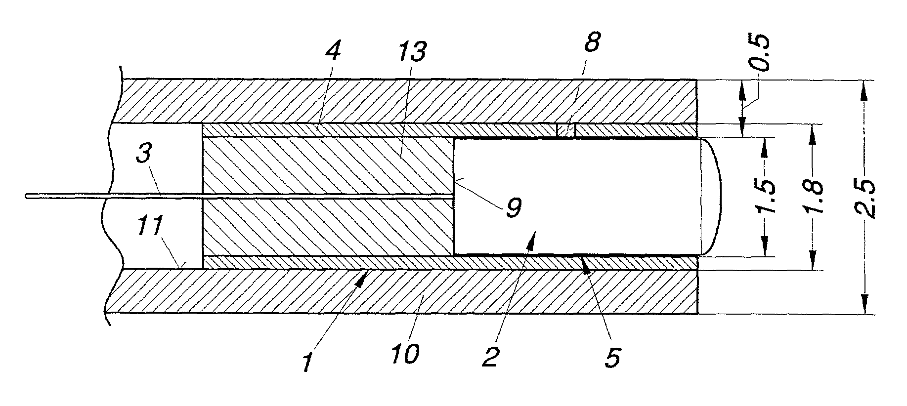
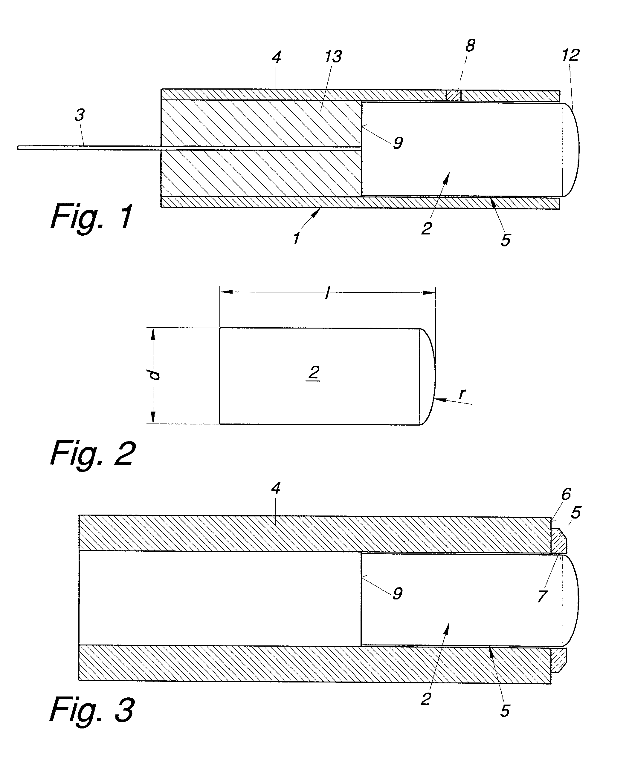
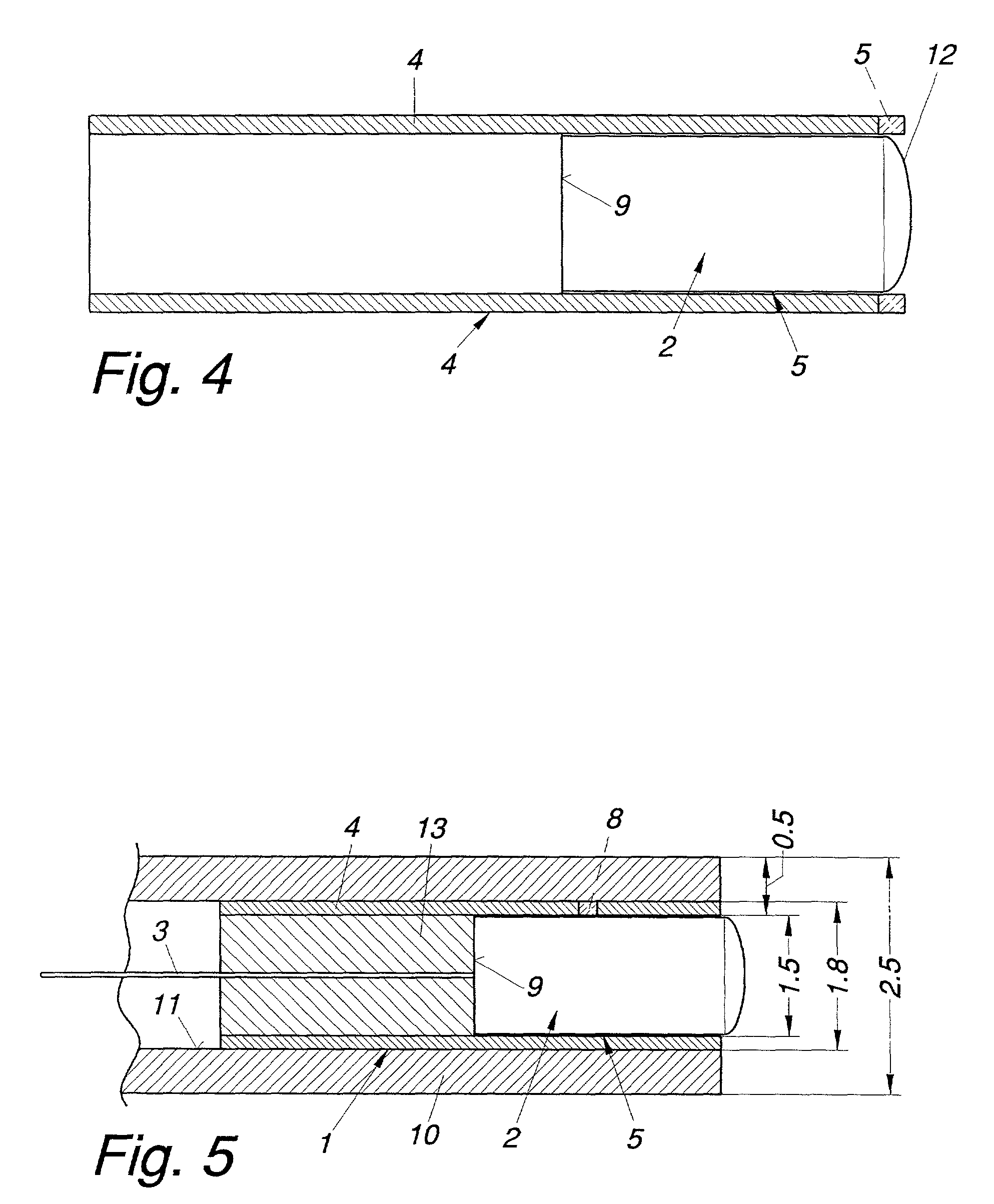
[0024]The exemplary optical sensor 1 of FIG. 1 serves for the monitoring of combustion processes in a combustion chamber and is provided with a condenser lens as an optical element 2 on the side facing the combustion chamber, and an optical fiber or fiber bundle 3 on the opposite side. In the same manner the device may be used as an emitter for the purpose of introducing measuring or excitation radiation into the combustion chamber of an internal combustion engine.

[0025]The condenser lens and the optical fiber bundle 3 (for example, a row of fibers located in a plane normal to the drawing plane) are jointly positioned in a tubular metal sleeve 4. Between the cylindrical optical element 2 and the inside of the metal sleeve 4 an annular gap is provided which is filled with solder material 5 (the cylindrical optical element 2 is coaxial with a longitudinal central axis of the metal sleeve 4). The optical element 2 made of sapphire is configured as a piano-convex rod-shaped lens and sol...


PUM


Abstract

An optical sensor or emitter (1) used for monitoring combustion processes in a combustion chamber is provided with an optical element (2) on a side facing the combustion chamber and an optical fiber or fiber bundle (3) on a side opposite the combustion chamber, the optical element and optical fiber/fiber bundle being jointly held in a metal sleeve (4). An annular gap filled with solder material (5) is provided between the optical element (2) and the inside of the metal sleeve (4).

Description

BACKGROUND OF THE INVENTION[0001]The invention relates to an optical sensor or emitter used for monitoring combustion processes in a combustion chamber, preferably during operation of an internal combustion engine, which is provided with an optical element on the side facing the combustion chamber and an optical fiber or fiber bundle on the side opposite of the combustion chamber, which are jointly held in a metal sleeve, and to a process for manufacturing such optical sensors.DESCRIPTION OF PRIOR ART[0002]The above sensors are employed in the field of engine development, for example, to study the temporal and spatial development of combustion processes. In EP 0 593 413 B1, for instance, an optoelectronic measuring device is disclosed in which the sensors are located in the cylinder head gasket of an internal combustion engine. The individual optical sensors, which may be combined into groups, each have a spherical lens of quartz or sapphire which is in contact with an optical fiber...

Claims


Application Information

Patent Timeline
IPC IPC(8): G01L23/22F02D35/00G01J1/02F23N5/08G01J5/08G01M15/10G02B6/32
CPCF23N5/08G01J5/0014G01J5/04G01J5/042G01M15/10G01J5/048G01J5/08G01J5/0803G01J5/0806G01J5/0821G01J5/0893G01J5/046F23N2029/00G01J5/024F23N2229/00
Inventor PHILIPP, HARALDWINKLHOFER, ERNST
Owner AVL LIST GMBH
Why Eureka
Try Eureka