Grounded molding tool for manufacture of optical components

a technology of optical components and molding tools, which is applied in the field of injection molding of optical components, can solve the problems of significant static electricity in the molten thermoplastic injection molding process, the relatively expensive mastering process, etc., and achieve the effects of improving grounding, reducing or eliminating and reducing the amount of charge passing

Inactive Publication Date: 2006-03-07
IMATION
View PDF27 Cites 2 Cited by
  • Summary
  • Abstract
  • Description
  • Claims
  • Application Information

AI Technical Summary

Benefits of technology

[0007]In general, the invention is directed to an injection molding tool that has improved grounding. The injection molding process creates significant amounts of static electricity in the molten thermoplastic material. This static electricity can be more adequately dissipated from the system through the addition of one or more conductive paths to ground. In this manner, a significant reduction in charge passing between the stamper and the mirror block can be achieved. By reducing or eliminating the amount of charge passing between the stamper and the mirror block, erosion of the mirror block can be reduced or avoided. Reduction or avoidance of mirror block erosion can significantly improve the longevity of the mirror block and maintain the quality of optical components produced by a mold that incorporates the mirror block.
[0010]The invention is capable of providing several advantages. For example, the invention can increase the number of molding cycles that can be performed before a mirror block requires resurfacing. In addition, the invention may also prolong the life of stampers used in molding tools. In both cases, by increasing the number of molding cycles that can be performed before the molding tool requires maintenance, the per-component cost of injection molding can be significantly reduced.

Problems solved by technology

The mastering process is a relatively expensive process in which a photoresist is coated on a master substrate, exposed to electromagnetic radiation to develop a photoresist pattern, and then removed in the non-developed regions.
The injection molding process creates significant amounts of static electricity in the molten thermoplastic material.

Method used


Image

  • Grounded molding tool for manufacture of optical components
  • Grounded molding tool for manufacture of optical components
  • Grounded molding tool for manufacture of optical components

Examples


example

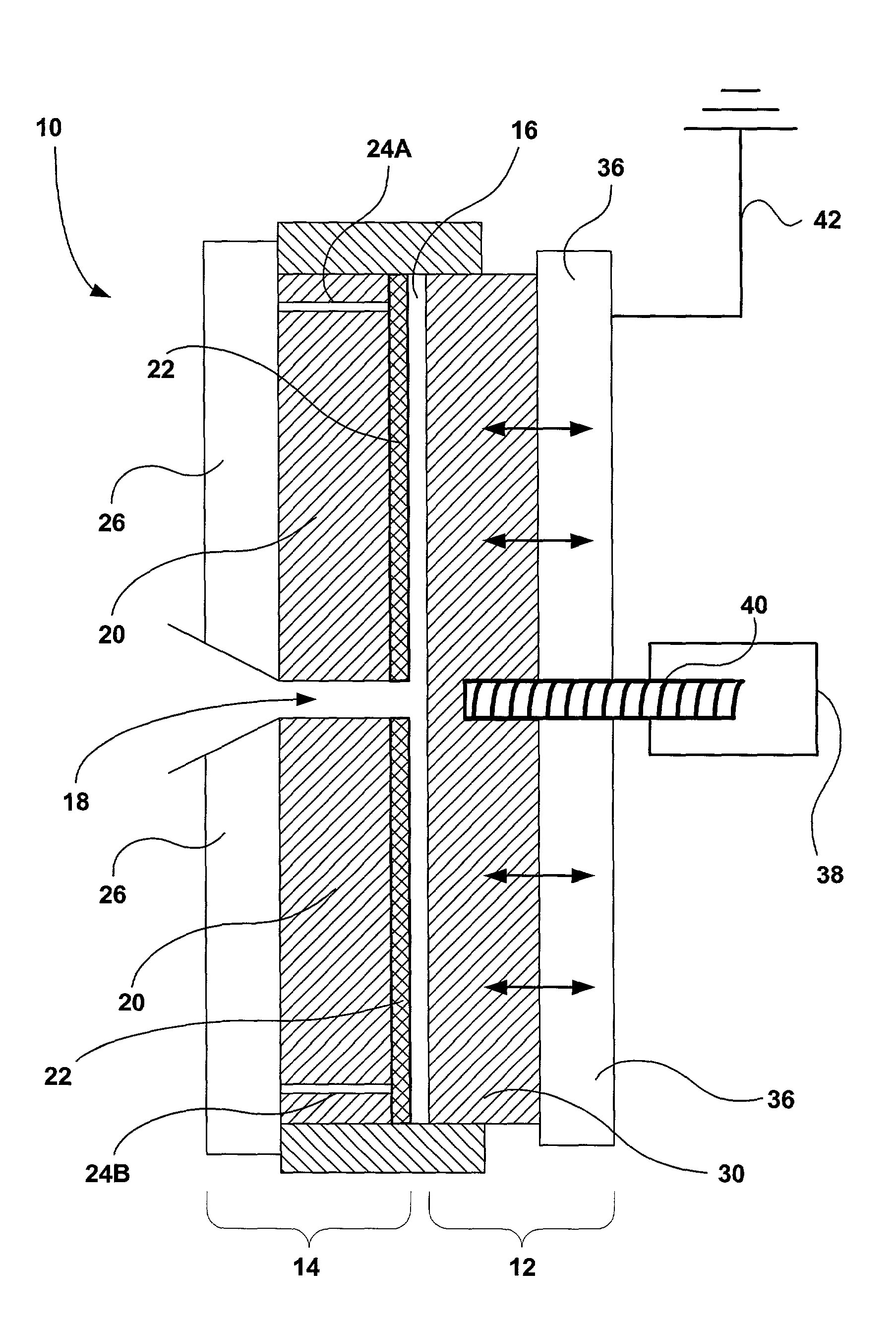
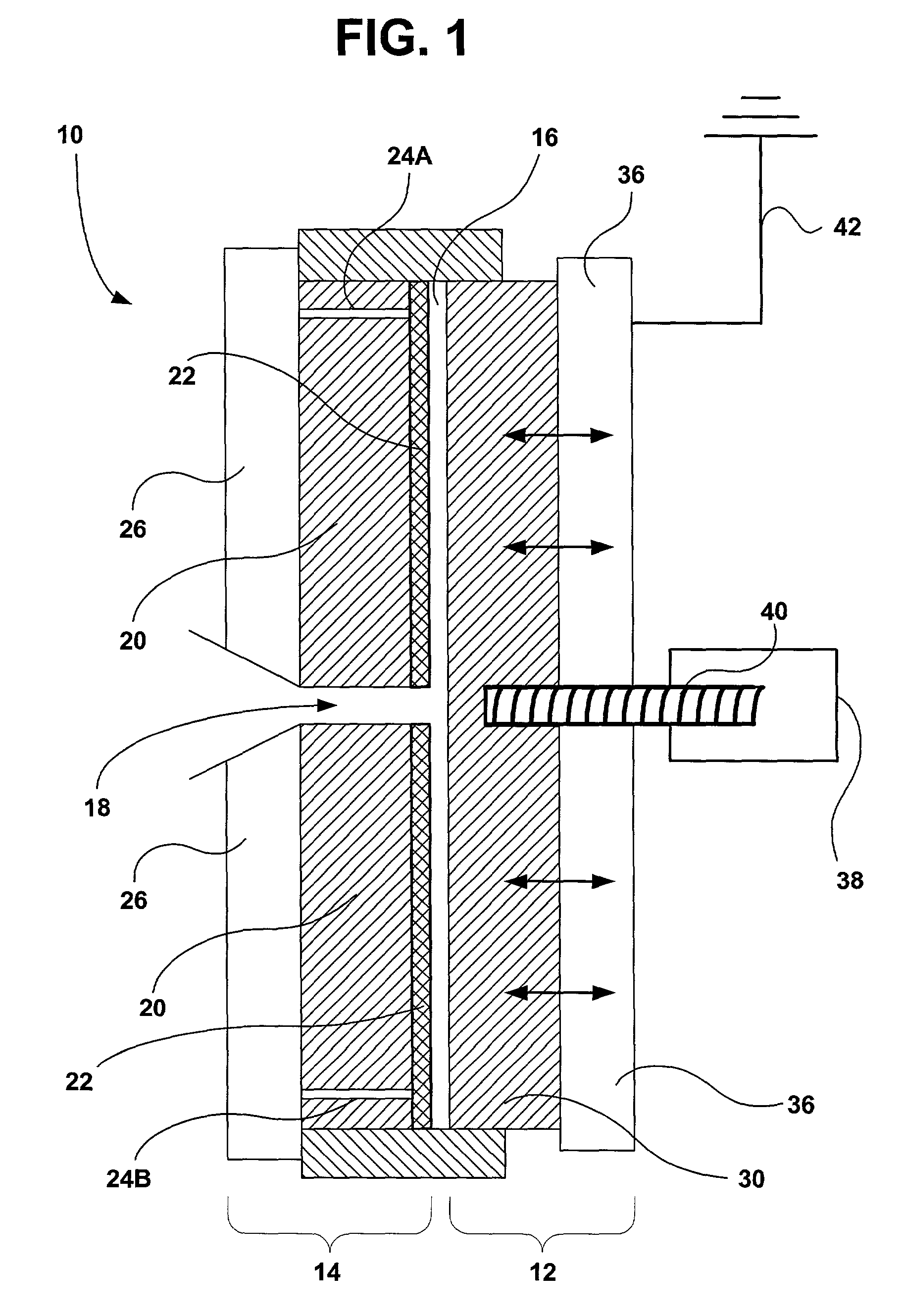
[0028]Sumitomo CD-RW Molding System, model number SD 40, commercially available from Sumitomo Plastics-Machinery of Norcross, Ga. was used to mold optical data storage disks. A molding tool within the Sumitomo CD-RW Molding System operated in a manner similar to the description above with reference to FIG. 1. However the molding tool originally did not include the substantially non-resistive path to ground 42.

[0029]In that case, the life cycle of the mirror block adjacent the vacuum drawn stamper was only approximately 75,000 molding cycles. After 75,000 cycles, the mirror block required resurfacing because of erosion. Resurfacing of a mirror block may take approximately four to six weeks and typically costs approximately $4000. Given the number of molding cycles, erosion in the mirror block was adding more than $0.05 of cost to each molded data storage disk.

[0030]The erosion pattern of the eroded mirror block was examined under a microscope. The microscopic inspection revealed that...


PUM

PropertyMeasurementUnit
pressuresaaaaaaaaaa
grounded voltageaaaaaaaaaa
voltageaaaaaaaaaa

Abstract

In one embodiment, the invention is directed to an injection molding tool that has improved grounding. The injection molding process creates significant amounts of static electricity in the molten thermoplastic. This static electricity can be more adequately dissipated from the system through the addition of one or more paths to ground. In this manner, a significant reduction in charge passing between the stamper and the mirror block can be achieved. By reducing or eliminating the amount of charge passing between the stamper and the mirror block, erosion of the mirror block can be reduced or avoided.

Description

TECHNICAL FIELD[0001]The invention relates to injection molding of optical components such as optical data storage disks.BACKGROUND OF THE INVENTION[0002]Injection molding tools can be used to create high quality optical components such as optical data storage disks. Optical data storage disks have gained widespread acceptance for the storage, distribution and retrieval of large volumes of information. Optical data storage disks include, for example, audio CD (compact disc), CD-R (CD-recordable), CD-ROM (CD-read only memory), DVD (digital versatile disk or digital video disk) media, DVD-RAM (DVD-random access memory), and various types of rewritable media, such as magneto-optical (MO) disks and phase change optical disks. Some newer formats for optical data storage disks are progressing toward smaller disk sizes and increased data storage density. Injection molding tools are also used to create other molded components such as optical components having a high quality reflective surfa...

Claims


Application Information

Patent Timeline
Patent Type & Authority Patents(United States)
IPC IPC(8): B29D11/00
CPCB29D17/005Y10S425/808
Inventor BANAL, ANTHONY O.HALL, GORDON L.KLUMPER, LORYN D.KOHOUT, KRAIG A.
Owner IMATION
Why Eureka
Try Eureka