High transmittance overcoat for microlens arrays in semiconductor color imagers

a technology of color imagers and microlens arrays, which is applied in the direction of optics, instruments, optical elements, etc., to achieve the effects of high transmittance, improved flexibility of design and layout of semiconductor array color imaging devices, and improved focus performan

Inactive Publication Date: 2006-03-07
TAIWAN SEMICON MFG CO LTD
View PDF7 Cites 33 Cited by
  • Summary
  • Abstract
  • Description
  • Claims
  • Application Information

AI Technical Summary

Benefits of technology

[0018]It is a principal object of the present invention to provide a manufacturable method and microelectronic fabrication process for making an ideal microlens having optimal focus performance and then overcoating at least one high transmittance film with refractive index near 1.5 on the said formed microlens to adjust the focal length within the available depth of focus design window.
[0019]A further object of the present invention is to increase flexibility of the design and layout of semiconductor array color imaging devices. The present invention obviates the need for electronic or optical changes to existing design and allows compensating adaptive adjustment with minimum processing to realize design specifications.
[0020]Another object of the present invention is to improve the electro-optic sensitivity and gain value of the long focal length microlens imager, and, provide a solution for super depth focal plane CMOS, CCD, and CID image sensors. Experimental performance comparison has shown that conventional microlens imager sensitivity varies in the order of 2.5 times the pixel fill-factor, while long focal length microlens imagers average 1.8 to 1.9 times the fill-factor, where fill-factor is defined as photodiode sensing area divided by pixel area (size). The high transmittance (>95%) overcoat process of the present invention has been experimentally demonstrated to yield effective gain values for long focal length microlenses of over 2.0 times the pixel fill-factor.
[0021]Another object of the present invention is to provide an adaptive process wherein antireflection and image-forming structures, spectral color filters, and, combinations or varying configurations of semiconductor vertical profiles can be integrated with the result of maximizing collection efficiency of image intensity patterns on the photodiode planar arrays to achieve optimum pixel resolution and color signal contrast.
[0022]Another object of the present invention is to provide an overcoat process allowing the widest and most forgiving process windows for microlens and semiconductor integration for high reproducibility, high reliability, and, consequently maximum process yield and minimum production cost.

Problems solved by technology

The design challenge is, therefore, how to get the most surface area of the lens and keep the focal length constrained in the available design window.

Method used


Image

  • High transmittance overcoat for microlens arrays in semiconductor color imagers
  • High transmittance overcoat for microlens arrays in semiconductor color imagers
  • High transmittance overcoat for microlens arrays in semiconductor color imagers

Examples


Embodiment Construction

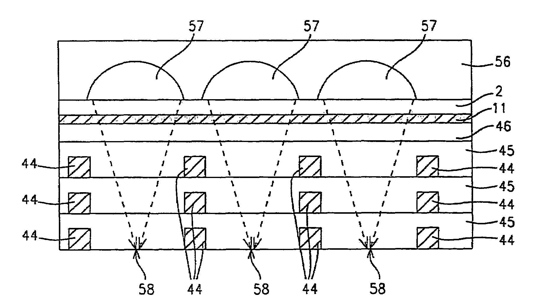
[0042]The present invention discloses a simple fabrication sequence and the specific optical conditions and materials properties to be satisfied in forming an overcoat of high transmittance material to optimize long focal length microlens arrays for integrated semiconductor array color imaging devices.

Process Flow

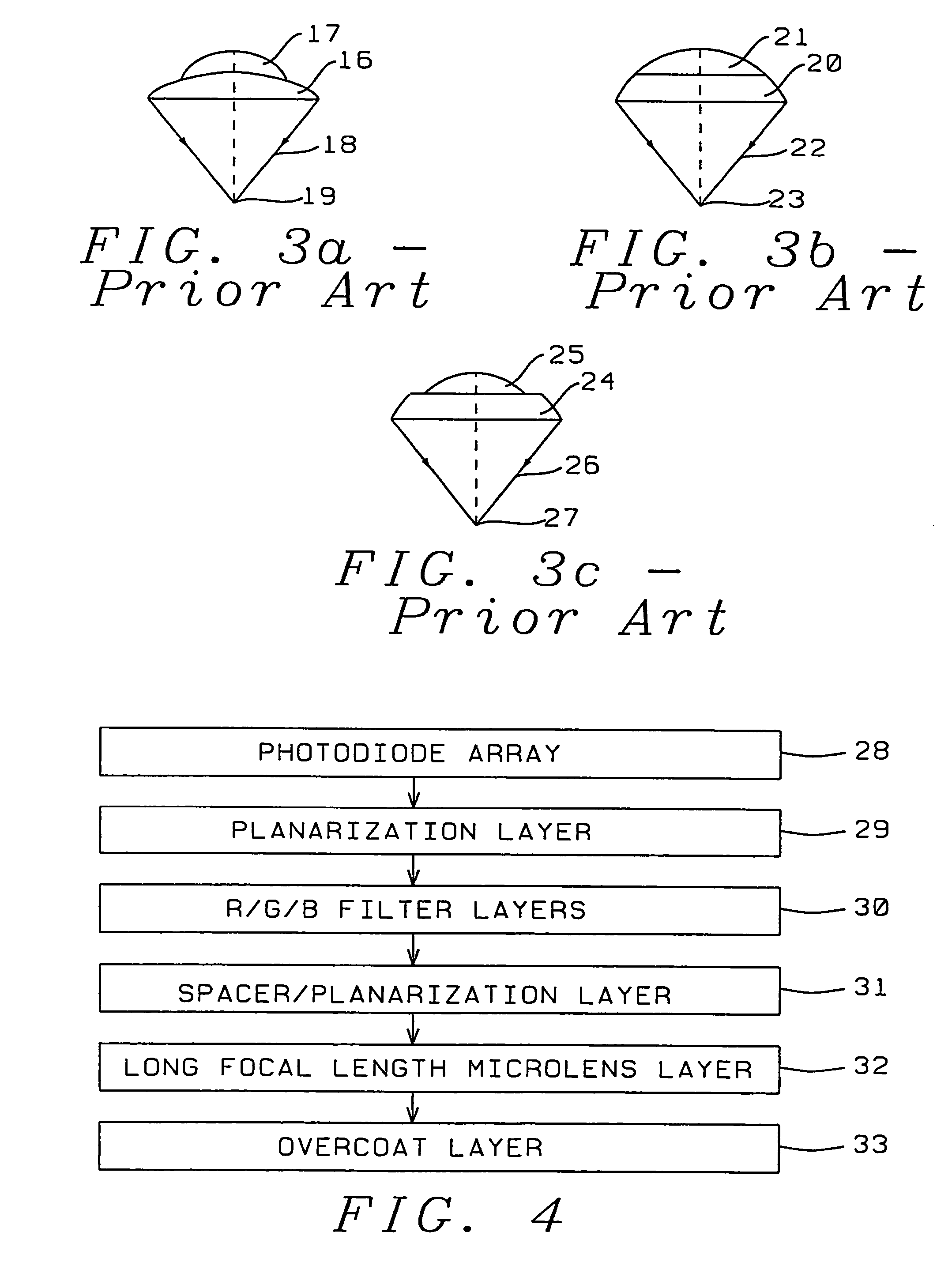
[0043]FIG. 4 depicts the simplified fabrication flow-chart of the process of the present invention, ordered in steps 28 through 33. In step 28 an array of image circuits having photosensitive areas are provided on a semiconductor substrate. In step 29 the array is coated with a transparent layer for passivation purposes which is planarized to accept the fabrication of an optical structure. This layer includes the necessary light shielding layers each with a planarization layer. In step 30 color filter layers are formed. In the preferred embodiment, three color layers are formed as detailed in FIG. 12. In step 31 another planarization (spacer) layer is formed which provides ...


PUM


Abstract

A transmittance overcoat with effectively planar top surface and specified optical and materials properties is applied above a microlens layer to extend the focal length and enhance the performance of long focal length microlenses for semiconductor array color imaging devices. The geometrical optics design factors and microelectric fabrication sequence to achieve optimized long focal length microlens performance are disclosed. The principal advantages of the adaptive process taught in the present invention is shown to enable real-time compensation adjustments for process and material variations. The overcoat process enables simplified single-layer integrated microlens optics for low-cost, high volume manufacturing of CMOS and CCD color video cameras.

Description

CROSS-REFERENCE TO RELATED APPLICATION[0001]This is a continuation of U.S. patent application Ser. No. 09 / 633,644, filed Aug. 7, 2000 now U.S. Pat. No. 6,821,810, titled “High Transmittance Overcoat for Optimization of Long Focal Length Microlens Arrays in Semiconductor Color Imagers,” by Hsiao et al., the entire contents of which is hereby incorporated by reference.BACKGROUND OF THE INVENTION[0002](1) Field of the Invention[0003]The present invention relates to the optical design and microelectronic fabrication of high transmittance overcoat material(s) to increase focal length and optimize performance of long focal length microlens arrays in semiconductor color imagers.[0004](2) Description of Prior Art[0005]Semiconductor array color image sensors for video cameras are conventionally comprised of complementary metal-oxide semiconductor (CMOS), charge-coupled devices (CCD), or, charge-injection devices (CID) integrated with optical structures consisting of planar arrays of microlen...

Claims


Application Information

Patent Timeline
Patent Type & Authority Patents(United States)
IPC IPC(8): G02B27/10H01L21/00H01L31/0203H01L31/0232
CPCH01L27/14621H01L31/0232H01L27/14627H01L27/14623H01L31/02327
Inventor HSIAO, YU-KUNGPAN, SHENG-LIANGCHANG, BII-JUNOLU, KUO-LIANG
Owner TAIWAN SEMICON MFG CO LTD
Why Eureka
Try Eureka