Apparatus and method of CTCM encoding and decoding for a digital communication system

a digital communication system and encoder technology, applied in the field of encoders and decoders for digital communication systems, can solve the problems of error coding complexity, price to be paid, translation, etc., and achieve the effect of optimizing energy efficiency

Inactive Publication Date: 2006-03-07
OHIO UNIV
View PDF14 Cites 81 Cited by
  • Summary
  • Abstract
  • Description
  • Claims
  • Application Information

AI Technical Summary

Benefits of technology

[0028]In accordance with one aspect of the present invention, a method of building systematically a multi-dimensional (n, D, L) circular trellis coded modulation (CTCM) encoder with properties of optimal energy efficiency, strong tail biting and maximum minimum distance (dmin) of trellis paths, where n is the size of the symbol alphabet, D is the depth of the trellis, and L is the length of the information symbol sequence comprises the steps of: (a) identifying simplex-transition sets of originating and next states for each stage i of the circular trellis; (b) determining butterfly structures associated with the identified simplex-transition sets wherein the originating and next states of said simplex-transition sets are arranged in an internal order within said butterfly structures; (c) aligning said butterfly structures into a multi-dimensional state transition matrix (STM) in a predetermined order; (d) constructing a simplex of channel symbols from a multi-dimensional signal constellation space for each of said identified simplex-transition sets; (e) aligning each simplex into a multi-dimensional initial input simplex (IIS) matrix in an order in relation to said predetermined order of butterfly structures in said STM; and (f) assigning channel symbols to state transitions of a trellis path by mapping between said simplex-transitions of the STM and said simplexes of said IIS matrix.

Problems solved by technology

Error correction codes embedded in or redundant to the data codes assist in this process, but there is always a price to be paid as the performance is drawn closer and closer to the Shannon limit.
This price includes error coding complexity which translates into higher costs and bandwidth or coding rate.
As error codes become more and more complex, greater and greater computing power is needed which translates into dollars.
In the real world, a channel may be either power limited or bandwidth limited and there are always trade-offs to be made depending on the application with regard to the type of error correcting codes to be used and the complexity thereof.
It is understood that block codes may be made to correct as many errors as desired, but at a price, which is a deterioration of code rate.
In addition, since the capacity or block of information bits is fixed in length, there may be much waste of resources.
Accordingly, wasted transmission capacity will result for all shorter words, especially those substantially shorter than the longest word.
However, because of the redundancy introduced by the code, this reduced distance no longer determines the error performance.
Orthogonal and bi-orthogonal signal constellations were researched, but they are not optimal for power limited channels.
But no systematic way to build the signal constellation and the symbol assignment therefor has of yet been described.
As a result, the error distance property of these codes cannot be analyzed systematically for practical use.
In addition, efficient decoding has not been investigated for these codes heretofore.
The BCJR algorithm is also considered optimal in that it minimizes the probability of symbol (or bit) error, but is much less popular than Viterbi algorithm and is almost never applied in practical systems.
The reason for this is that it yields performance in terms of symbol error probability only slightly superior to the Viterbi algorithm, yet it presents a much higher complexity.
This is obviously not desirable for large trellis.

Method used


Image

  • Apparatus and method of CTCM encoding and decoding for a digital communication system
  • Apparatus and method of CTCM encoding and decoding for a digital communication system
  • Apparatus and method of CTCM encoding and decoding for a digital communication system

Examples


example 1

[0073]Take CTCM (4,3) as an example. The state transition table for this example is shown in Table 1 of FIG. 9. The states are numbered by integer from 1 to 64. It can be found that any member of the set of states{1, 64, 4, 33} can transit to state 1, 2, 5, and 34. Then, the set of states {1, 64, 4, 33} and the set of states {1, 2,5, 34} build a butterfly with such states being the originating states set and the next states set of this butterfly, respectively. This butterfly may be written as butterfly {[1, 64, 4, 33], [1, 2, 5, 34]}. All 16 butterflies may be identified from Table 2 and are illustrated in FIG. 10, where each box represents a butterfly. The originating state set and next state set are in the left side and right side of a butterfly, respectively. By this representation, we regard a butterfly as an ordered structure and refer to a particular arrangement of the states in a butterfly as the internal order of a butterfly. For this example, the location of the state (or t...

example 2

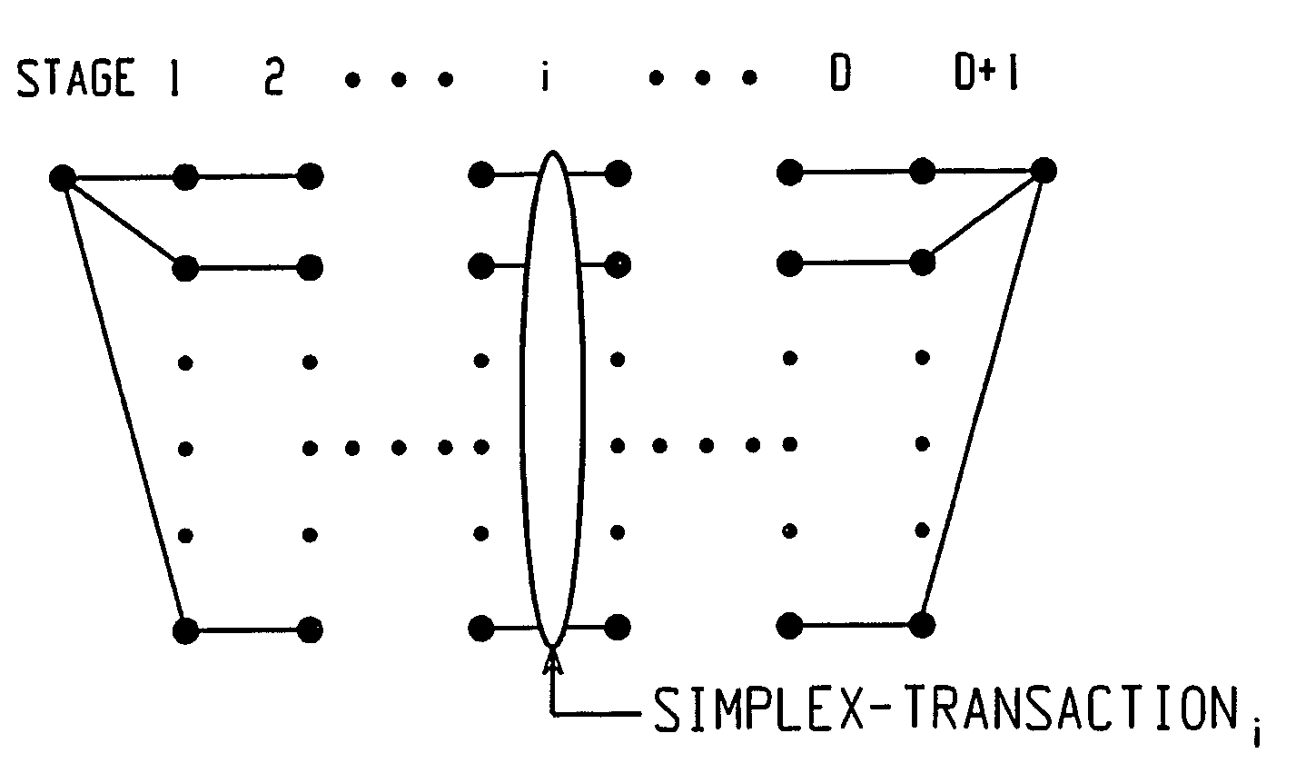
[0075]For CTCM (4,3), Table 2 of FIGS. 12A–12C illustrates all of the 256 paths (rows of the table) for L=D+1=4, wherein the numbers in the columns of a row represent the states along a path with the starting state to the extreme left of each row and the ending state to the extreme right thereof. Transitions originate from states of column i to next states of the adjacent column going from left to right, said transitions representing the state transitions at stage i. The set of 4 state transitions at a stage i on the paths associated with a starting state constitute a simplex-transitioni; for each i, i=1, 2, 3, 4. Note that for this example, there are 64 simplex-transitioni's; for each stage i, i=1, 2, 3, 4.

[0076]For instance, on the 4 paths associated with starting state 3, the set of state transitions at stage 2 (i.e. transitioning states between column 2 and column 3 of Table 2) constitute a simplex-transition2 denoted as simplex-transition2 {4→1, 14→3, 10→6, 50→35}. For a partic...

example 3

[0082]For a CTCM (4,3), compare all the simplex-transitions's from Table 2 of FIGS. 12A–12C with all its 16 butterflies as shown in FIG. 10. For instance, on the 4 paths associated with starting state 3 of the first stage, the simplex-transition1 {3→4, 3→14, 3→10, 3→50}, is contained in butterfly 3, as shown in FIG. 13(a). The simplex-transition4 {2→3, 14→3, 7→3, 36→3} of the last stage is contained in butterfly 2, as shown in FIG. 13(b). The 4 transitions in simplex-transition2 {4→1, 14→3, 10→6, 50→35} of a middle stage are contained in butterflies 1, 2, 4, and 10, respectively as shown in FIG. 13(c). Also, it can be verified that the other 15 transitions in each of the butterflies 1, 2, 4, and 10 constitute the other 15 simplex-transition2's. (end of example)

[0083]In general, for a CTCM (n, D), the following property is observed for a simplex-transitioni, of the middle stages, i.e. 2≦i≦D.

[0084]Property 1

[0085]Consider two simplex-transitioni's: if the originating state (or next st...


PUM


Abstract

A method of building systematically a multi-dimensional (n, D, L) circular trellis coded modulation (CTCM) encoder with properties of optimal energy efficiency, strong tail biting and maximum minimum distance (dmin) of trellis paths is disclosed. In addition, a communication system for use in a power limited channel application is disclosed comprising a circular trellis coded modulation (CTCM) encoder with permuted state structure for encoding based on a circular trellis path associated with a sequence of digital information bits and a set of simplexes identified for the path from a multi-dimensional signal constellation; a transmitter coupled to said CTCM encoder for transmitting said sequence of channel symbols over said channel; a receiver for receiving a transmission from said transmitter including said sequence of channel symbols and any noise induced therein; and a CTCM decoder coupled to said receiver for decoding the received transmission without knowledge of the starting state of the circular trellis path of the CTCM encoder to recover the sequence of information bits. Apparatus and methods of encoding and decoding are also disclosed utilizing a combination of circular trellis-coded modulation with permuted state structure and simplex signal constellation techniques for use in the digital communication system.

Description

GOVERNMENT RIGHTS CLAUSE[0001]The U.S. Government may have certain rights in the present invention as a result of work performed under and / or for the following Air Force contracts: F30602-96-C-0176 and F30602-99-C-0064.BACKGROUND OF THE INVENTION[0002]The present invention is directed to encoders and decoders for a digital communication system, in general, and, more particularly, to apparatus and method of encoding and decoding utilizing a combination of circular trellis-coded modulation with permuted state structure and simplex signal constellation techniques for use in a digital communication system.[0003]In a digital communication system such as shown by way of example in the block diagram schematic of FIG. 1, digital data information is provided by a source 10 in a coded information sequence to a channel encoder 14. Channel coding in encoder 14 transforms the information sequence to a sequence of code symbols called a code sequence or code word. The transformation is designed to...

Claims


Application Information

Patent Timeline
Patent Type & Authority Patents(United States)
IPC IPC(8): H04L5/12H03M13/25H03M13/39H03M13/41
CPCH03M13/25H03M13/39H03M13/6505H03M13/413H03M13/6502H03M13/4123
Inventor DILL, JEFFREY C.LOPEZ-PERMOUTH, SERGIO R.LINDSEY, ALAN RAYLO, YUNG-CHENGALDER, FRANK A.SONG, XIANGYU
Owner OHIO UNIV
Why Eureka
Try Eureka