Fiber optical attenuator

a technology of optical attenuators and fibers, which is applied in the field of optical attenuators, can solve the problems of strong attenuation and device differences, and achieve the effects of strong attenuation, low manufacturing cost and simple construction and operation

Inactive Publication Date: 2006-03-07
II VI DELAWARE INC
View PDF7 Cites 7 Cited by
  • Summary
  • Abstract
  • Description
  • Claims
  • Application Information

AI Technical Summary

Benefits of technology

[0011]The present invention seeks to provide a new variable fiber optical attenuator which is compact, polarization insensitive, operable at low voltage, wavelength independent, simple in construction and operation, and of low manufacturing costs. The attenuator utilizes the cut-off phenomenon for single mode propagation of an optical wave down a single mode fiber. It is known that the dimensions of a single mode fiber are such that it can only support the lowest order mode of propagation, which is generally the fundamental mode, ideally having a Gaussian cross section. A wave with a higher order mode cannot propagate down the small dimension of the single mode fiber, and thus suffers strong attenuation.

Problems solved by technology

A wave with a higher order mode cannot propagate down the small dimension of the single mode fiber, and thus suffers strong attenuation.
In this respect, the device is quite different from the prior art devices of Wang et al., wherein phase change is effected by change in the bulk refractive index itself of the propagation medium.

Method used


Image

  • Fiber optical attenuator
  • Fiber optical attenuator
  • Fiber optical attenuator

Examples


Embodiment Construction

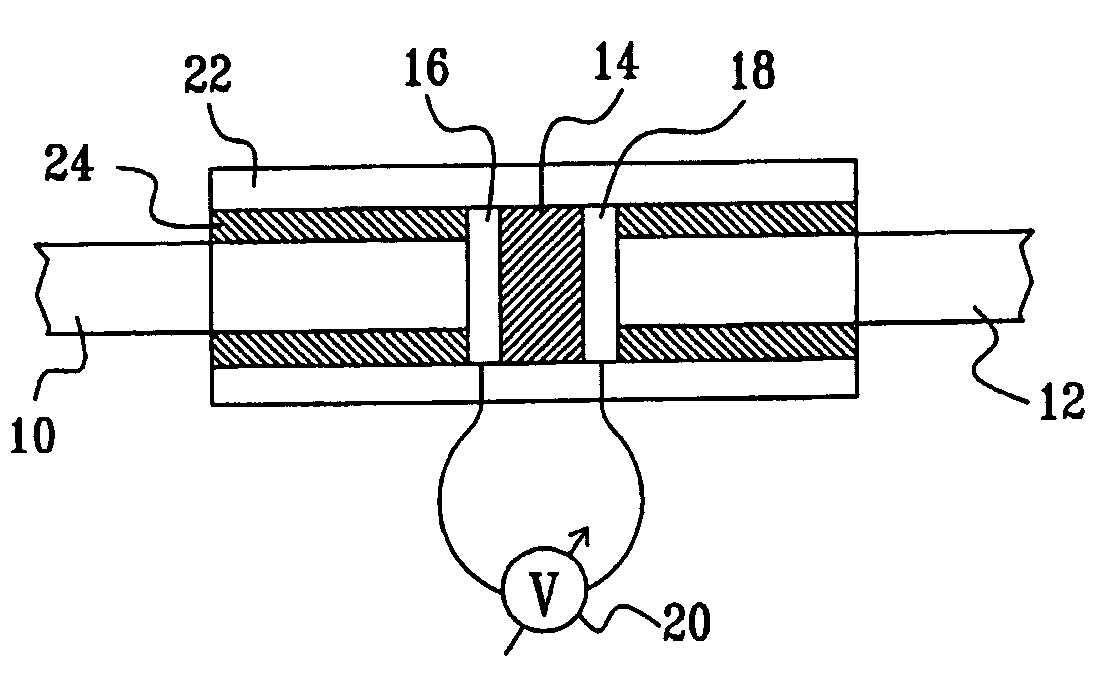
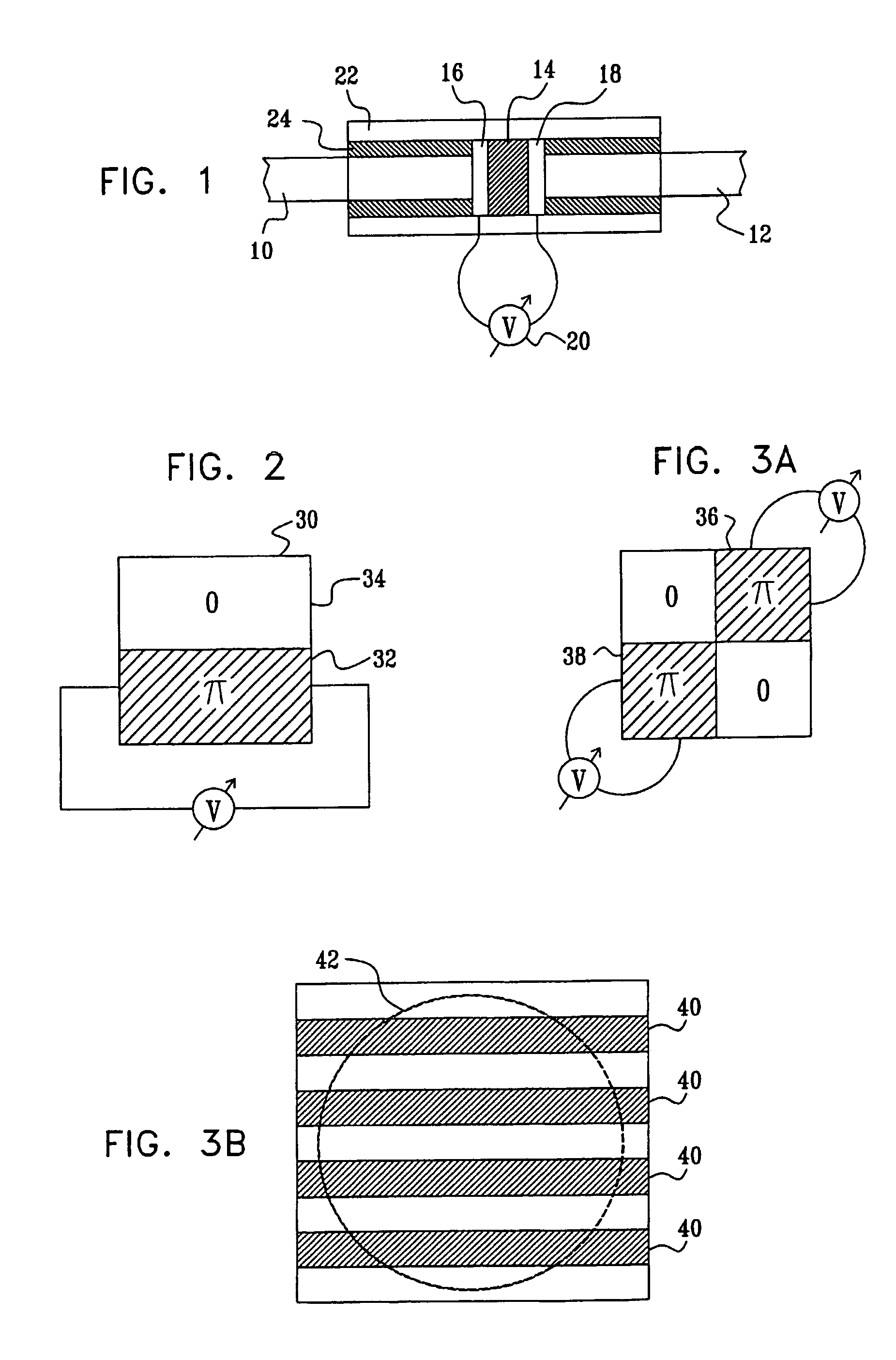
[0058]Reference is now made to FIG. 1, which illustrates schematically a variable fiber optical attenuator, constructed and operative according to a preferred embodiment of the present invention. The attenuator consists of two sections of single-mode optical fiber 10, 12, between whose ends is disposed a liquid crystal element 14, such that light passing from the end of one of the fibers to the other must traverse the liquid crystal film. The liquid crystal element 14 preferably has transparent electrodes 16, 18 deposited on its faces, such that switching can be simply accomplished by application of a variable voltage 20 across the electrodes. The electrodes are pixelized (not visible in this side view, but shown in FIGS. 2 and 3A and 3B below), so that preselected sections of the liquid crystal element can be switched separately. The fiber end sections and the liquid crystal element are rigidly held in contact, preferably by means of an external sleeve 22, and a sealant material 24...


PUM

PropertyMeasurementUnit
twist angleaaaaaaaaaa
total twist angleaaaaaaaaaa
phaseaaaaaaaaaa

Abstract

A fiber optical attenuator utilizing the cut-off phenomenon for single mode propagation of an optical wave down a single mode fiber, comprising an element such as a pixelated liquid crystal element, capable of spatially changing the phase across the cross section of an input optical signal. Such a spatial phase change is equivalent to a change in the mode structure of the propagating wave. The signal propagating in the single mode output fiber is attenuated in accordance with the extent to which higher order modes are mixed into the low order mode originally present. When the mode is completely transformed to higher order modes, the wave is effectively completely blocked from entering the output single-mode fiber, and the attenuation is high. The level of attenuation is determined by the fraction of the wave which is converted to modes other than the lowest order mode, and is thus controllable by the voltage applied to the pixels of the liquid crystal element.

Description

[0001]This patent application is a continuation of International Application No. PCT / IL02 / 00188 which was filed Mar. 8, 2002 and designates the United States of America. This International Application was published in English under International Publication No. WO 02 / 071133.FIELD OF THE INVENTION[0002]The present invention relates to the field of optical attenuators, and especially electronically variable attenuators suitable for use in fiber optical applications.BACKGROUND OF THE INVENTION[0003]Variable attenuators are important components in fiber optical test and measurement instrumentation and in fiber optical communication systems. The requirements of optical attenuators for use in such systems are that they should vary the intensity of the light transmitted without appreciably altering the spatial, temporal, spectral or polarization distribution of the light beam, and that they should be polarization insensitive.[0004]Many types of variable attenuators have been described in t...

Claims


Application Information

Patent Timeline
Patent Type & Authority Patents(United States)
IPC IPC(8): G02B6/00G02B6/26G02F1/065G02F1/01G02F1/13G02F1/1333G02F1/1343G02F1/139H01S3/10H04B10/07H04B10/27H04B10/29H04B10/294H04B10/40H04B10/50H04B10/60H04J14/00H04J14/02
CPCG02F1/0115G02F1/1326G02F1/2955G02B6/266G02F1/134309G02F2203/48G02F2201/04G02F2201/17G02F1/1396
Inventor COHEN, GIL
Owner II VI DELAWARE INC
Why Eureka
Try Eureka