Signal processor
a technology of signal processor and circuit components, applied in the direction of electrical control, machines/engines, instruments, etc., can solve the problems of affecting the effect of circuit component numeric value fluctuations and the inability to achieve the purpose of improvemen
- Summary
- Abstract
- Description
- Claims
- Application Information
AI Technical Summary
Benefits of technology
Problems solved by technology
Method used
Image
Examples
first preferred embodiment
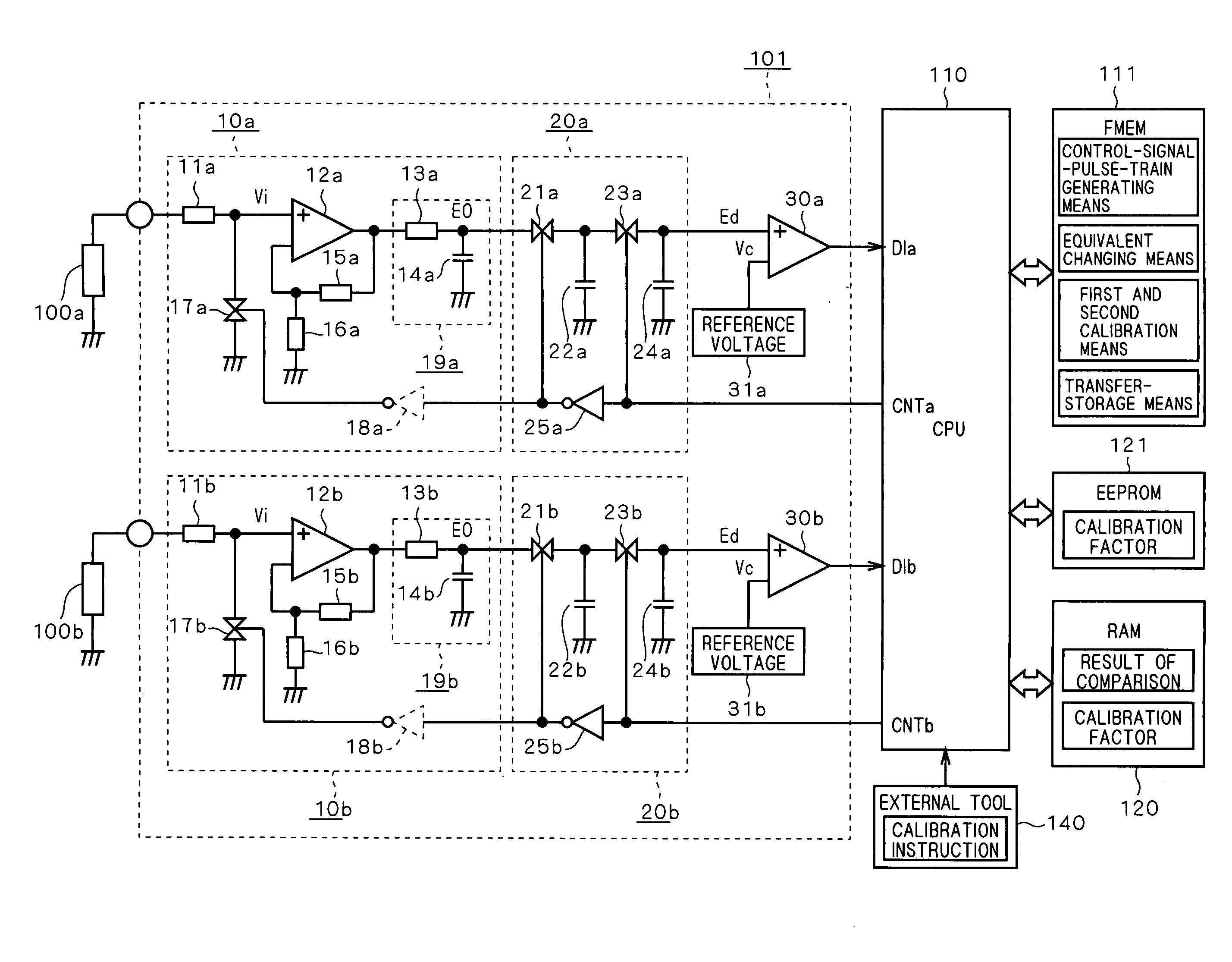
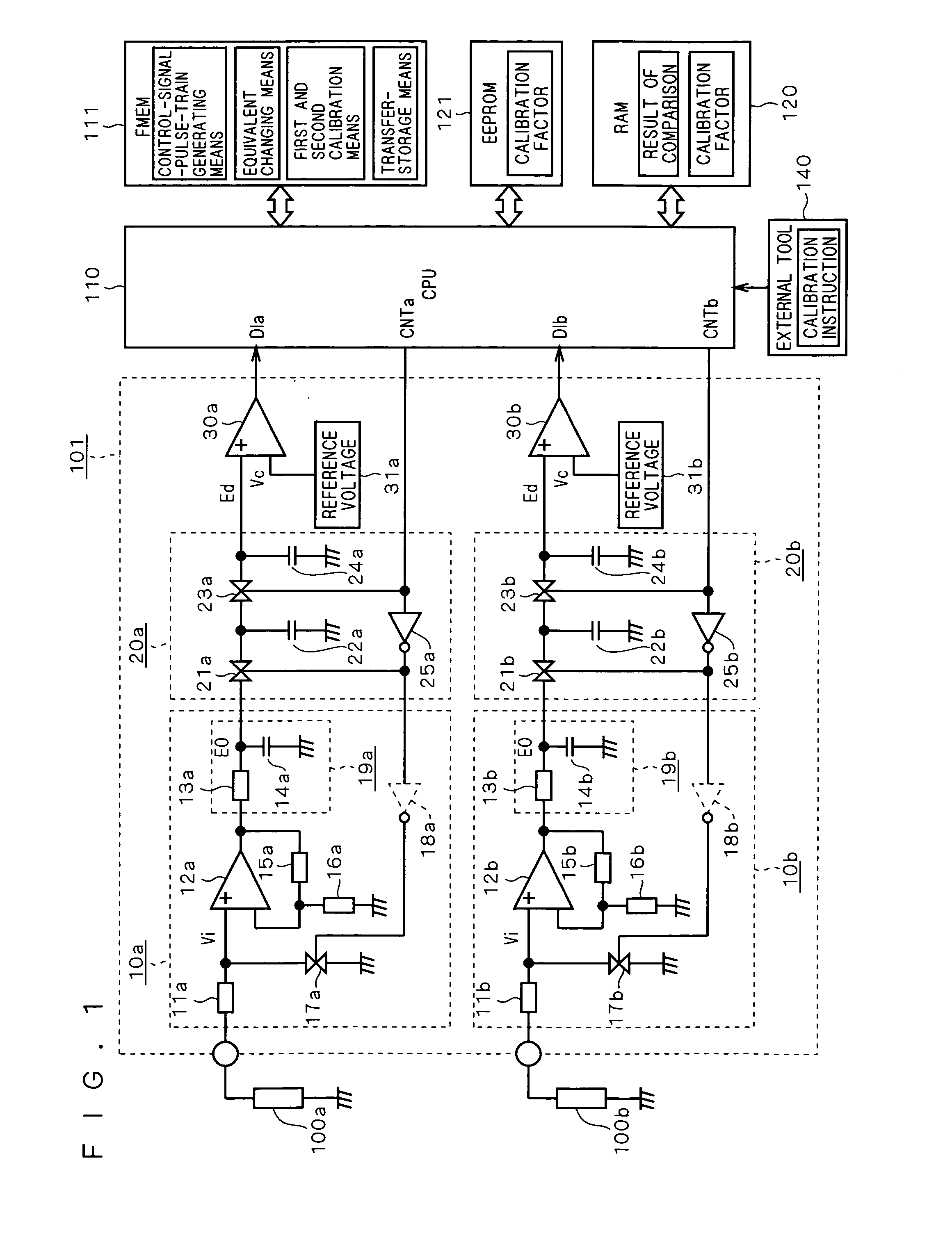
[0026]FIG. 1 is a circuit diagram of a signal processor according to the present embodiment. The following discussion is provided in reference to FIG. 1. An analog input signal processor 101 shown in FIG. 1 is provided between variable analog signal sources 100a, 100b and a microprocessor 110. The analog input signal processor 101 according to the present embodiment is formed by gain control circuits 10a, 10b, switched capacitor filter circuits 20a, 20b each constituting a low-pass filter circuit, and analog comparator circuits 30a, 30b serving as data converters. Output voltages of the analog signal sources 100a and 100b as input to the analog input signal processor 101 are compared with standard reference voltages 31a and 31b, respectively, and the results are input to the microprocessor 110 as digital logic signals DIa and DIb, respectively.
[0027]Now, the gain control circuit 10a will be described in detail. The gain control circuit 10a includes an amplifier 12a with an input res...
second preferred embodiment
[0070]FIG. 5 is a circuit diagram of a signal processor according to the present embodiment. In FIG. 5, an analog input signal processor 102 is provided between variable analog signal sources 100c, 100d and the microprocessor 110. The analog input signal processor 102 according to the present embodiment includes a gain control circuit 10c, a switched capacitor filter circuit 20c constituting a low-pass filter circuit, analog comparator circuits 30c, 30d serving as data converters and a multiplexer 40c. The results of comparisons between the analog signal source 100c and standard reference voltages 31c, 31d are input to the microprocessor 110 as digital logic signals DI1 and DI2, respectively, and are stored in the RAM memory 120.
[0071]The multiplexer 40c switches connection from the variable analog signal source 100c to the variable analog signal source 100d in response to a connection switching signal MPX generated by the microprocessor 110. With this switching, the comparisons are...
third preferred embodiment
[0080]FIG. 6 is a circuit diagram of a signal processor according to the present embodiment. The following discussion of the signal processor shown in FIG. 6 is focused on differences from that shown in FIG. 1. First, in the signal processor shown in FIG. 6, an analog input signal processor 103 is provided between the variable analog signal sources 100a, 100b and the microprocessor 110. The analog input signal processor 103 is formed by the gain control circuits 10a, 10b, switched capacitor filter circuits 20a, 20b each constituting a low-pass filter circuit and an AD converter 50 serving as a data converter. The signal voltages from the analog signal sources 100a and 100b are converted to digital form at the AD converter 50 and are input to the microprocessor 110.
[0081]The gain control circuits 10a, 10b and switched capacitor filter circuits 20a, 20b are the same as those shown in FIG. 1. However, the AD converter 50 is provided in place of the analog comparator circuits shown in F...
PUM
| Property | Measurement | Unit |
|---|---|---|
| output voltage V0 | aaaaa | aaaaa |
| voltage Vt | aaaaa | aaaaa |
| voltage | aaaaa | aaaaa |
Abstract
Description
Claims
Application Information
 - R&D
- Intellectual Property
- Life Sciences
- Materials
- Tech Scout
- Unparalleled Data Quality
- Higher Quality Content
- 60% Fewer Hallucinations
Browse by: Latest US Patents, China's latest patents, Technical Efficacy Thesaurus, Application Domain, Technology Topic, Popular Technical Reports.
© 2025 PatSnap. All rights reserved.Legal|Privacy policy|Modern Slavery Act Transparency Statement|Sitemap|About US| Contact US: help@patsnap.com


