Mobile HVAC cavity test device, method, and computer product

a cavity test and mobile technology, applied in the field of cavity pressure testing, can solve the problems of differential pressure decay system limited to large cavities and small cavities, system testing, and system damage, and achieve the effect of concentrating processing and effectively implementing a multi-tasking environmen

Inactive Publication Date: 2006-03-07
SCHNEIDER AUTOMATION INC
View PDF23 Cites 0 Cited by
  • Summary
  • Abstract
  • Description
  • Claims
  • Application Information

AI Technical Summary

Benefits of technology

[0012]The present invention advantageously provides a novel totalization of flow test system which features mobile test heads which communicate with a central processing system by way of wireless links. The present inventors have recognized that, in order for test systems which work in real-time to function reliably using relatively unreliable wireless links, the test heads themselves must be intelligent enough to carry on test procedures independently of the central processor. To accomplish this end, the present invention utilizes software algorithms and advanced processing capabilities which reside on the test head and which allow for the reliable testing of HVAC cavities independently from the central control system, and for the reliable transfer of commands and test results between the central control processor and the mobile test heads.
[0013]To resolve the issue of repeatability, typical testing conditions were observed and the present invention was designed with an “all things being equal” type of approach. Making assumptions as to the stability of temperature, pressure and temperature and utilizing temperature and pressure compensated mass flow meters, the present invention ensures repeatable results with nominal error.
[0014]In the present invention, during data acquisition, real-time microprocessor based operations monitor and perform calculations to determine cavity integrity. The present invention performs this integrity check as quickly as possible. In attempting to optimize the integrity algorithms and data sampling accuracy, a trade off is necessary for single microprocessor based systems. To resolve this issue, the present invention uses multiple microprocessors. The primary microprocessor receives information from the secondary processors reporting cavity volume. This approach segregates processing and effectively implements a true multitasking environment. Using this approach, the present invention is also very robust in terms of maintaining data integrity throughout a testing process. The secondary microprocessors maintain the information locally until the primary processor has acquired and acknowledge data transfer. This is particularly important for systems that require mobility of the testing device and where interruptions in network traffic may occur. The present invention operates effectively when only 5% of successful network transmissions are present.

Problems solved by technology

A disadvantage of pressure decay systems is that the cavities or pressure lines to be tested must be first evacuated in order to perform the test, and further, the systems must be tested in the absence of pressurized flow.
Pressure decay systems are limited to small cavities and are affected by temperature, pressure, and humidity.
Differential pressure decay systems are limited to large cavities and are also affected by temperature, pressure, and humidity.
A disadvantage of the flow meter systems is that the test cycle time tends to be too long to be practical in a modem vehicle assembly line environment, where the target time for testing is approximately 45 seconds.
Mass flow rate systems are affected by humidity, cavity temperature, excessive cycle duration, and are limited to measuring large cavities.
A disadvantage, as recognized by the present inventors, of using test heads connected with cables is that moving the test heads from vehicle-to-vehicle is constrained by the length of the cable, and further, the number of test heads that may be attached to a vehicle may be limited because of the difficulty of placing the test heads which are encumbered by the attached cables.
However, the level of cost associated with this type of system is inappropriate for typical testing conditions.

Method used


Image

  • Mobile HVAC cavity test device, method, and computer product
  • Mobile HVAC cavity test device, method, and computer product
  • Mobile HVAC cavity test device, method, and computer product

Examples


Embodiment Construction

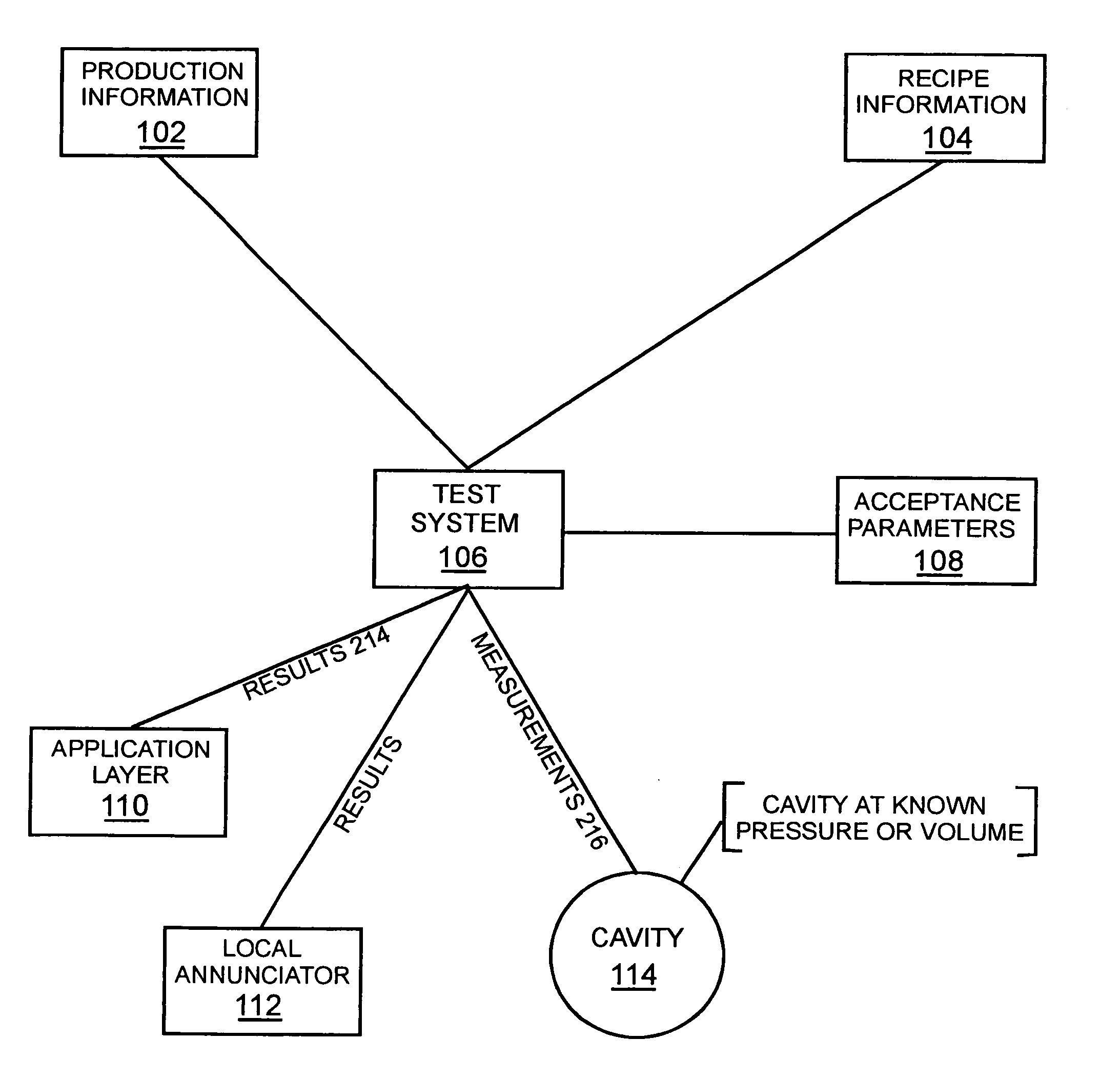
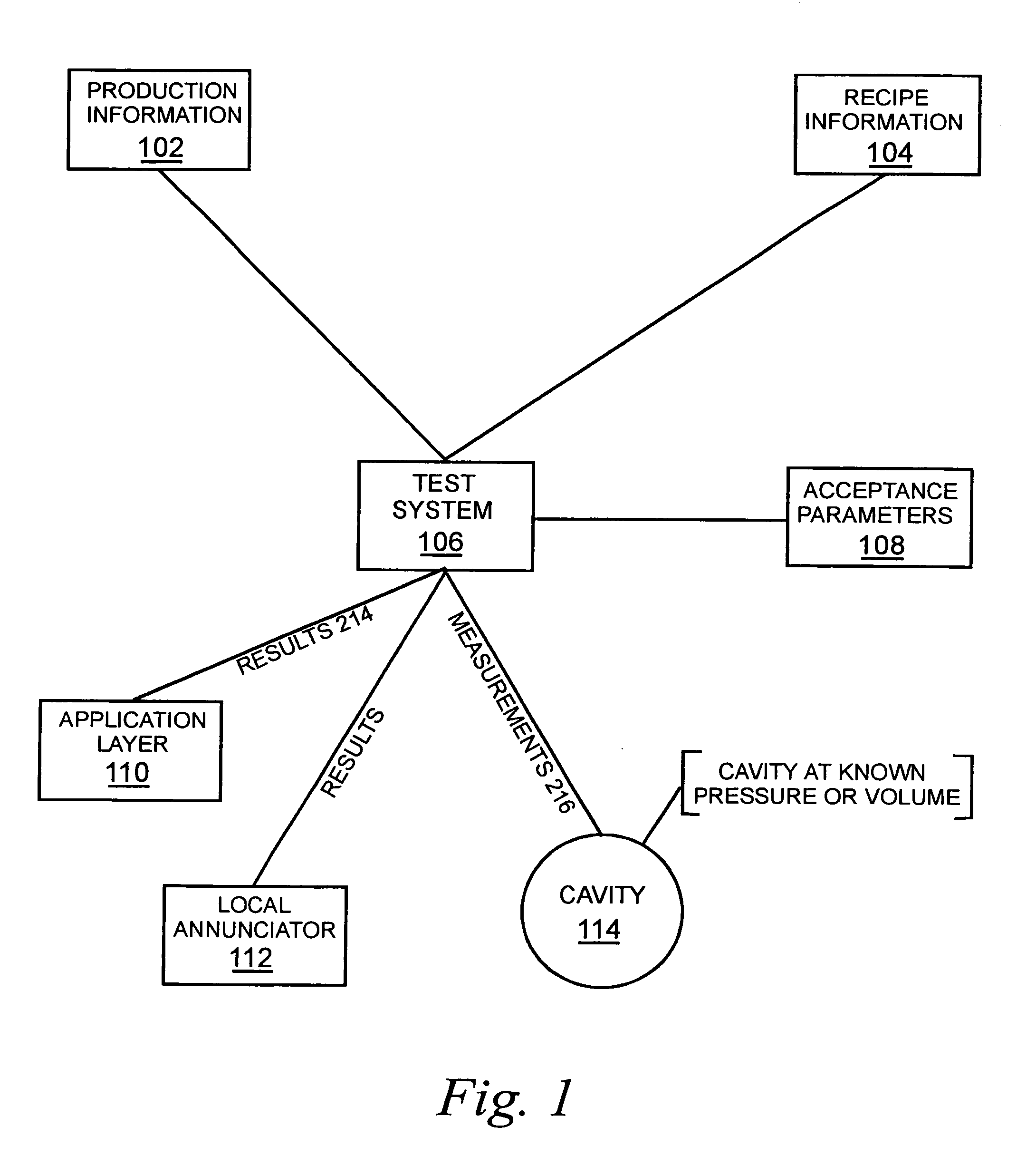
[0035]Referring now to the drawings, wherein like reference numerals designate identical or corresponding parts throughout the several views, FIG. 1 is a block diagram illustrating an example of the Test System 106 according to the present invention. The Test System 106 receives production information 102 and recipe information 104 from outside applications. Test System 106 conducts measurements 216 on cavity 114 which contains a volume of air at a known pressure or volume. The volume of air is compared against acceptance parameters 108 and the tested cavity is accepted or rejected. The result of the test is sent to outside applications 110 or to local enunciation devices 112.

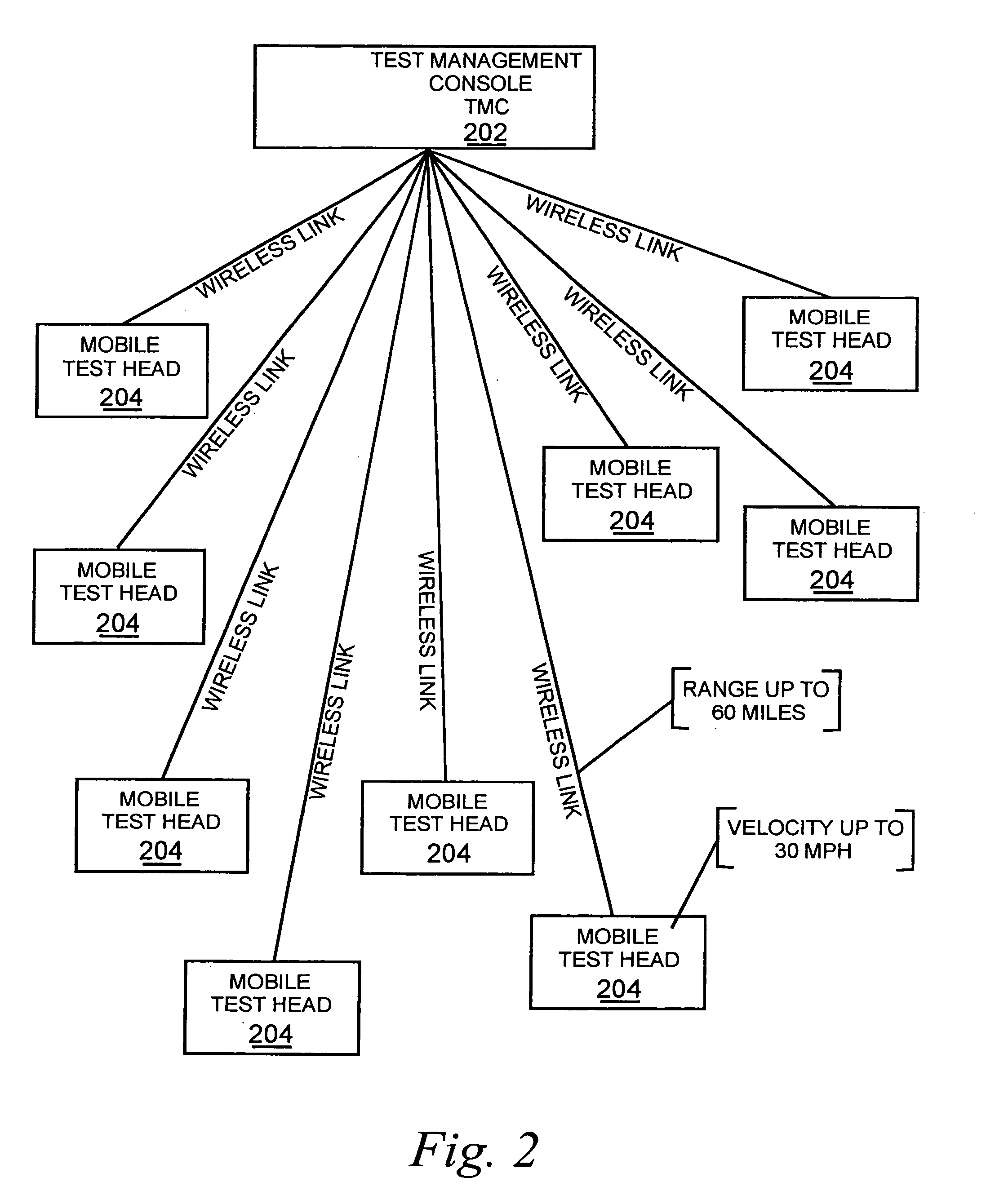
[0036]FIG. 2 is a block diagram illustrating an example of Test Management Console 202 communicating via wireless links with to up to 9 mobile test heads 204, where each mobile test head 204 may conduct an independent test simultaneously with tests performed by other mobile test heads. Each of the test heads 20...


PUM


Abstract

A mobile testing apparatus, method, and computer product that performs high speed testing of mobile pressure devices using high speed totalization, where testing of multiple devices may be done concurrently. Test results are communicated to a central console using a variety of communication methods, including wireless, and the testing apparatus and method is robust and reliable despite the occurrence of transient communication failures, because the test apparatus and method may operate independently of central control.

Description

CROSS REFERENCE TO RELATED APPLICATIONS[0001]This application claims the benefit of the earlier filing date of U.S. provisional patent application Ser. No. 60 / 307,386, filed Jul. 25, 2001, the entire contents of which are incorporated herein by reference.BACKGROUND OF THE INVENTION[0002]1. Field of the Invention[0003]The present invention relates to cavity pressure testing and particularly to HVAC testing of pressurized cavities in an assembly line environment.[0004]2. Discussion of the Background[0005]HVAC testing is widely employed in the manufacture of automotive vehicles which contain numerous vacuum and pressurized cavities throughout the structure of the vehicles, for example, air conditioning systems and engine systems. The efficient production of high-quality vehicles requires that the vacuum or pressurized systems be tested on the assembly line while the vehicles are being assembled. Because both accuracy and speed are required in this environment, manufacturers generally r...

Claims


Application Information

Patent Timeline
Patent Type & Authority Patents(United States)
IPC IPC(8): G21C17/00B60H1/00G01F17/00
CPCG01F17/00B60H1/00585
Inventor KUZALA, JOHN L.WERTHAM, MARK E.BELL, ROBERT J.HORVATH, PAUL G.
Owner SCHNEIDER AUTOMATION INC
Why Eureka
Try Eureka