Flat back case for an electrolytic capacitor

a technology of electrolytic capacitors and back cases, applied in the field of capacitors, can solve the problems of adding manufacturing costs and benefiting construction costs, and achieve the effects of reducing manufacturing costs, reducing construction costs, and reducing construction costs

Active Publication Date: 2006-03-14
WILSON GREATBATCH LTD
View PDF32 Cites 59 Cited by
  • Summary
  • Abstract
  • Description
  • Claims
  • Application Information

AI Technical Summary

Benefits of technology

[0004]In any event, the thusly-constructed capacitor has a planar shape at the cover. This benefits cost of construction, especially when a drawn process forms the casing portions. In conventional casings having mating “clamshells”, each portion comprises a major face wall supporting a surrounding sidewall. This means that two casing pieces must be drawn, which adds manufacturing costs. In some embodiments of the present casing only one of the mating casing portions is of a drawn construction. The cover is simply a stamped plate, which is easier and less costly to manufacture. Even in those embodiments where the cover plate is provided with a contoured profile, such as having the coinciding indentation, the drawn process is not nearly as costly as in the manufacture of a clamshell shaped portion. Additionally, the planar cover enables the capacitor to be easily positioned in a confined space, such as exists in an implantable medical device.

Problems solved by technology

This benefits cost of construction, especially when a drawn process forms the casing portions.
This means that two casing pieces must be drawn, which adds manufacturing costs.

Method used


Image

  • Flat back case for an electrolytic capacitor
  • Flat back case for an electrolytic capacitor
  • Flat back case for an electrolytic capacitor

Examples


Embodiment Construction

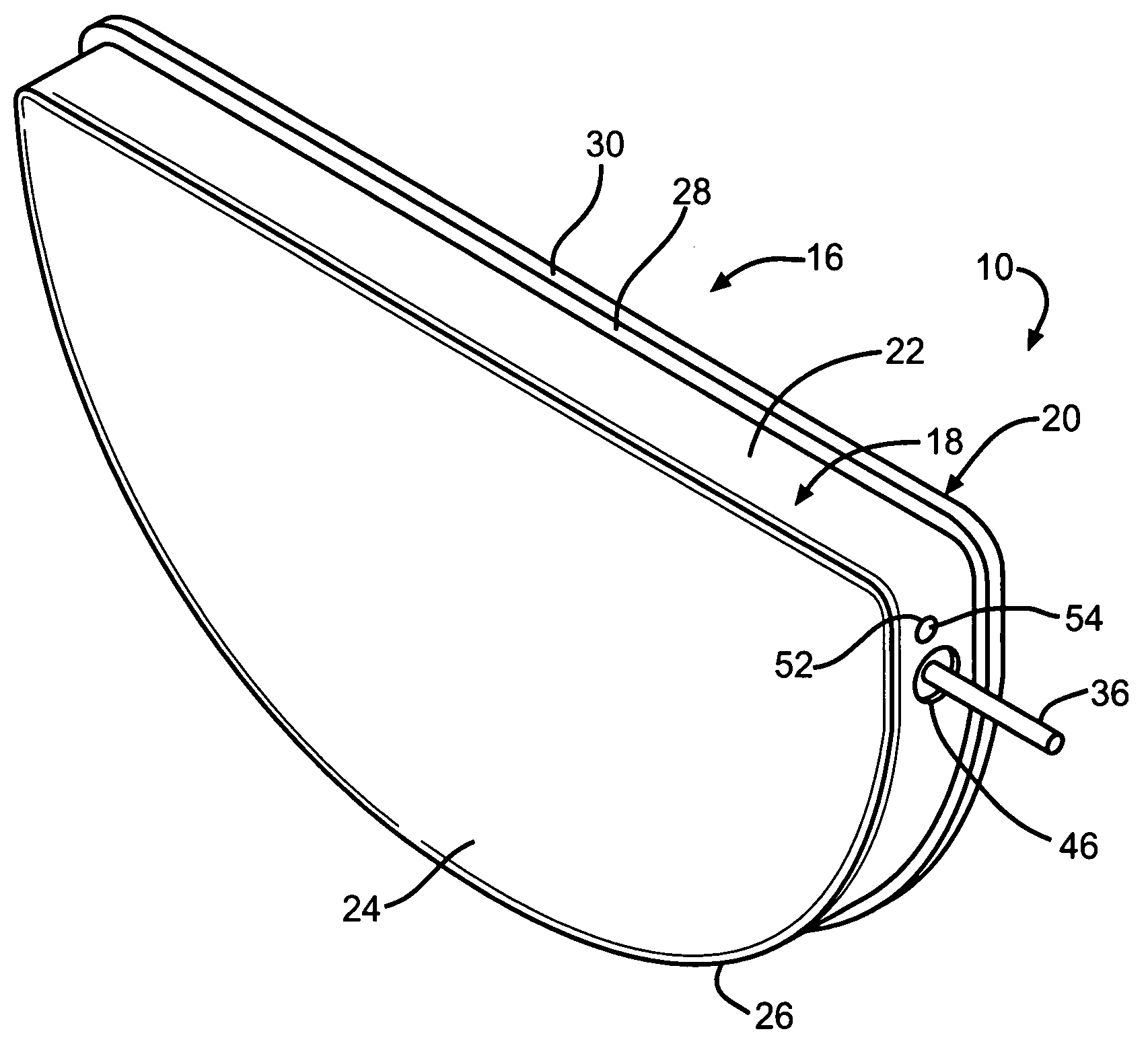
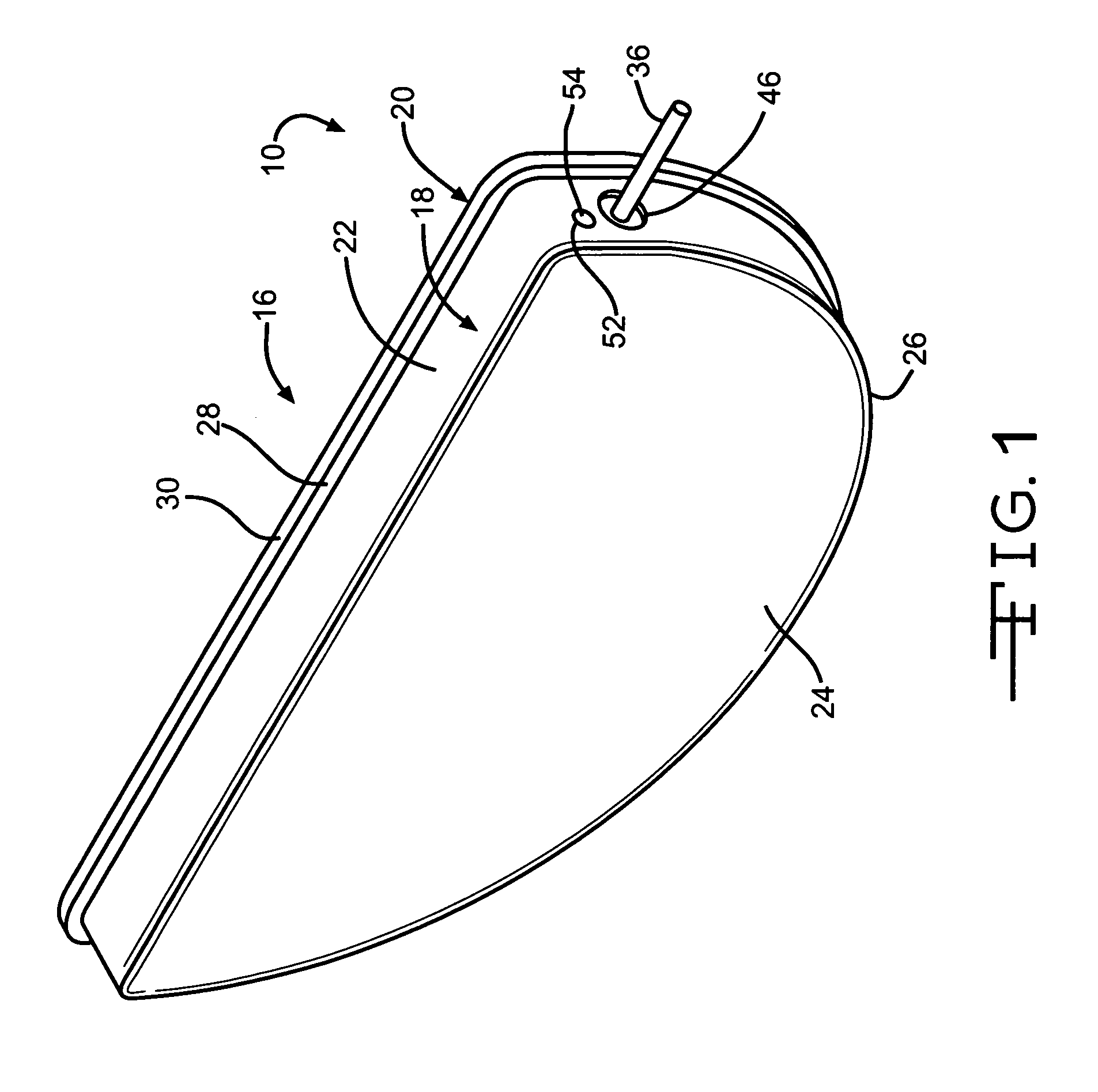
[0020]Referring now to the drawings, FIG. 1 is a perspective view showing a capacitor 10 according to the present invention. The capacitor 10 comprises an anode 12 (FIGS. 2 and 3) of an anode active material and a cathode of a cathode active material 14 housed inside a hermetically sealed enclosure 16. The capacitor electrodes are operatively associated with each other by a working electrolyte (not shown) contained inside the enclosure, as will be described in detail hereinafter. The capacitor 10 is of an electrolytic type with the cathode comprising a conductive material having capacitive properties.

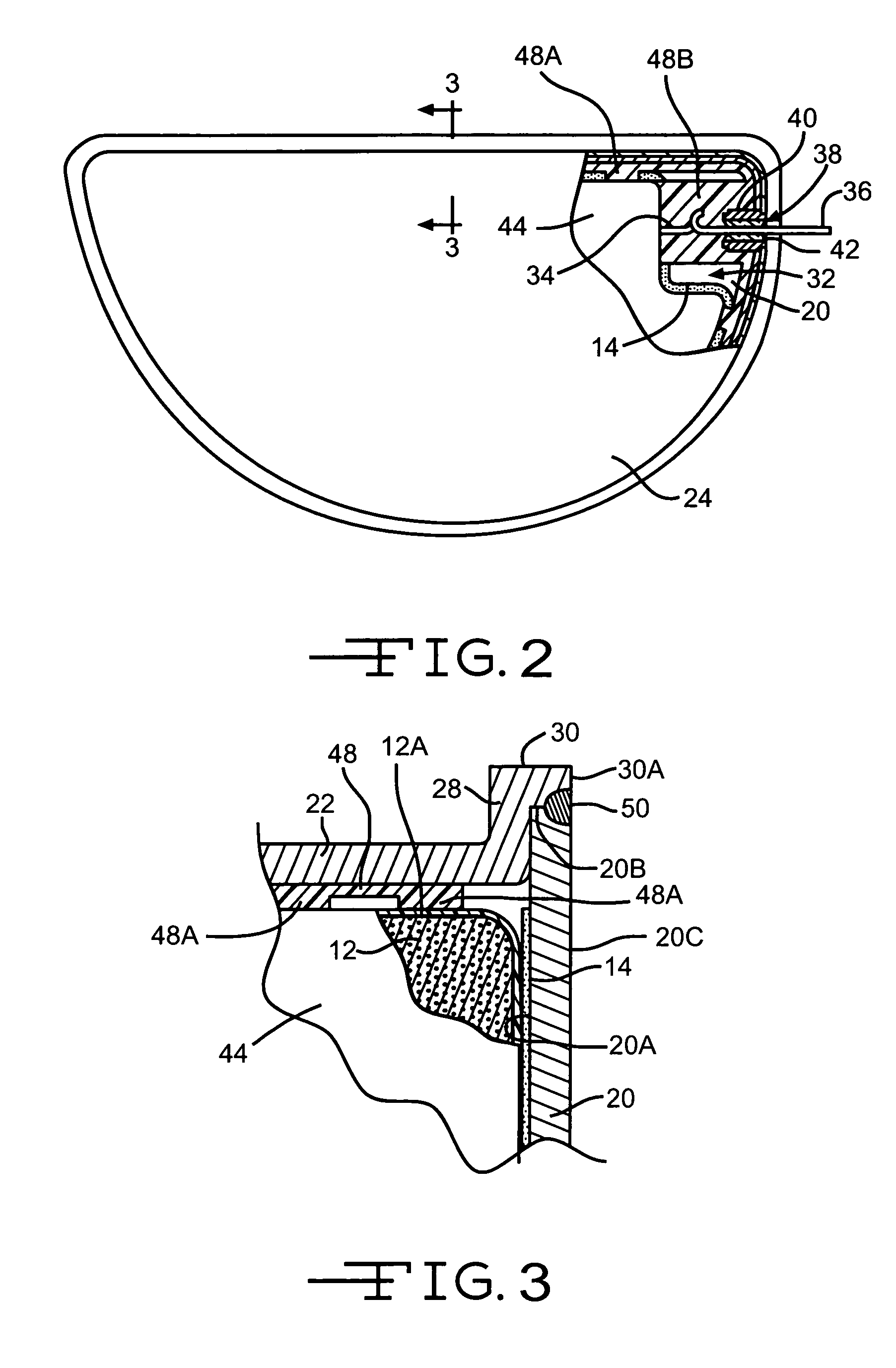
[0021]The enclosure 16 is of a metal material comprising first and second casing portions 18 and 20. Casing portion 18 is preferably of a drawn construction and comprises a surrounding sidewall 22 extending to and meeting with a face wall 24 at a curved intermediate bend 26. Opposite the bend 26, sidewall 22 forms into an upstanding surrounding web 28 extending to a rim 30. The web 28 a...


PUM

PropertyMeasurementUnit
thicknessaaaaaaaaaa
thicknessaaaaaaaaaa
thicknessaaaaaaaaaa

Abstract

An enclosure for an electrical energy storage device such as a wet tantalum electrolytic capacitor or an electrochemical cell such as a lithium / silver vanadium oxide cell is described. The enclosure comprises two metallic casing components or portions. The first is a drawn member having a planar face wall supporting a surrounding sidewall and is shaped to nest the anode, cathode and intermediate separator components. The surrounding sidewall has an annular flange at its outer periphery. A mating cover is a stamped planar piece of similar material whose periphery fits inside the annular flange or rim as a complementary piece.

Description

CROSS-REFERENCE TO RELATED APPLICATIONS[0001]The present application claims priority based upon U.S. provisional application Ser. Nos. 60 / 563,328 and 60 / 563,329, both filed Apr. 19, 2004.BACKGROUND OF THE INVENTION[0002]The present invention generally relates to a capacitor and, more particularly, to a capacitor capable of powering an implantable medical device, such as a cardiac defibrillator.SUMMARY OF THE INVENTION[0003]A casing for an electrolytic capacitor, such as a wet tantalum capacitor comprises two complementary metallic components or portions. The first has a planar face wall supporting a surrounding sidewall and is shaped to nest the anode, cathode and intermediate separator components. The surrounding sidewall has an annular flange at its outer periphery. A mating cover comprises a planar piece of similar material whose periphery fits inside the annular flange or rim as a complementary piece. In a second embodiment, the mating planar cover is provided with an indentatio...

Claims


Application Information

Patent Timeline
Patent Type & Authority Patents(United States)
IPC IPC(8): H01G2/10A61N1/375H01G9/00H01G9/06H01G9/08H01G9/10
CPCH01G9/06H01G9/10H01G9/08Y10T29/417Y02E60/13
Inventor MUFFOLETTO, BARRYGLOSS, EDWARD J.EBERHARD, DOUGLASSPAULDING, JOSEPHLIU, YANMINGNESSELBECK, NEALMARINACCIO, LOUISSTEMEN, ERICSTRINGHAM, RODNEY
Owner WILSON GREATBATCH LTD
Why Eureka
Try Eureka