

Optical disk apparatus using focal shift signals to control spherical aberration
a technology of optical disk and focal shift, which is applied in the direction of disposing/mounting heads, instruments, data recording, etc., can solve the problems of affecting the accuracy of optical disks, etc., to eliminate the adverse influence of axial shift, and facilitate assembly and adjustment
- Summary
- Abstract
- Description
- Claims
- Application Information
AI Technical Summary
Benefits of technology
Problems solved by technology
Method used
Image

Examples
embodiment 1
(Embodiment 1)
[0086]Referring now to drawing, an embodiment mode of the present invention will be described.
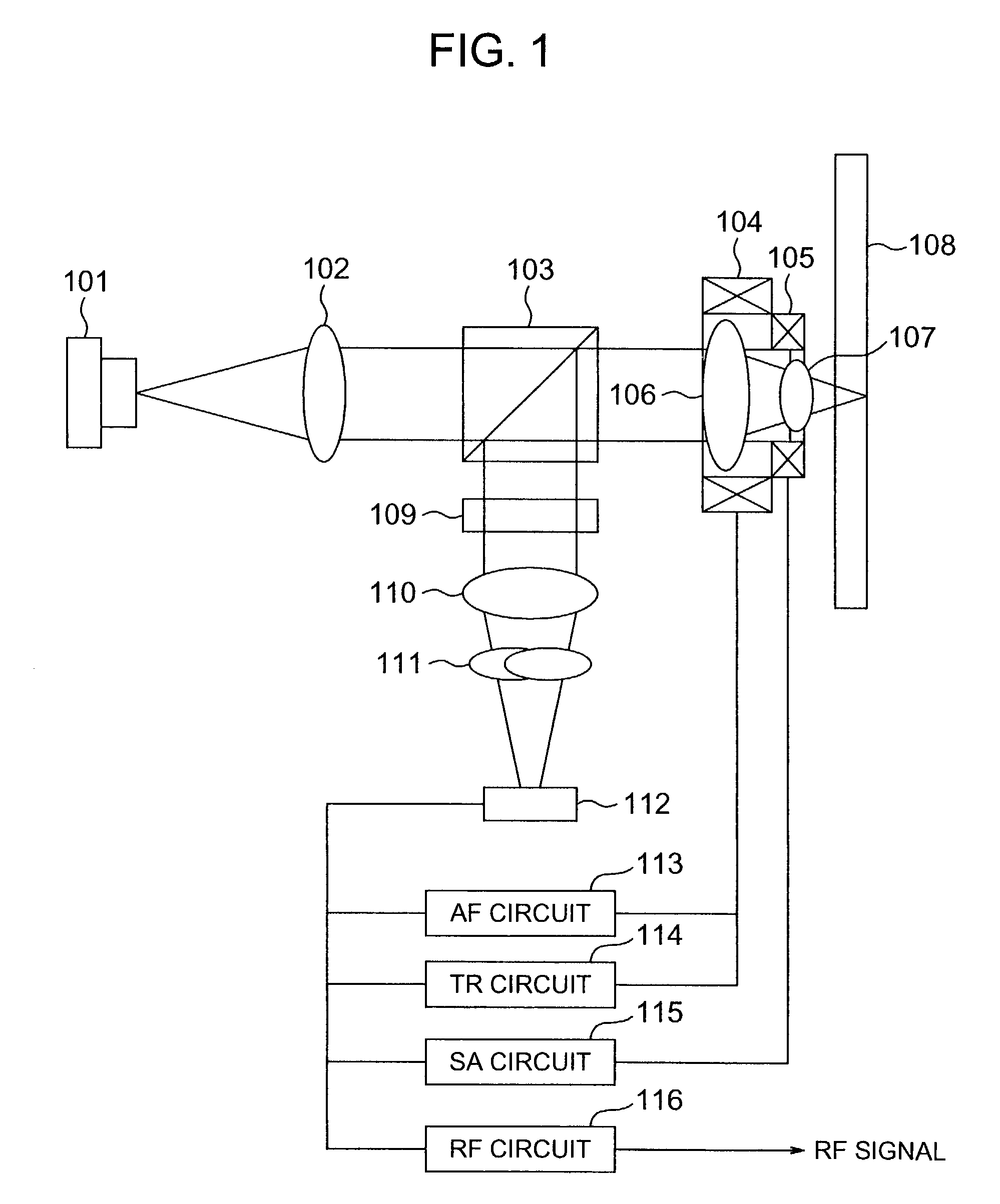
[0087]FIG. 1 schematically shows a basic embodiment mode of an optical disk apparatus according to the present invention.
[0088]Light emitted from a semiconductor laser 101 is collimated into parallel light by a collimating lens 102, and this collimated light passes through a beam splitter 103, and then this collimated light is condensed over a base plate onto a recording film plane of an optical disk 108 by a two-group / two-sheet of objective lenses 106 and 107. The beam splitter corresponds to a first optical branching element as recited in a claim. In the two-group / two-sheet of objective lenses, a first lens 106 is mounted on a two-dimensional actuator 104 and is driven along both an optical axis direction and a radial direction of the optical disk. The second lens 107 is mounted on a spherical aberration correcting actuator 105 which is driven in combination with the first l...
embodiment 2
(Embodiment 2)
[0102]FIG. 13 shows on optical disk apparatus according to an embodiment of the present invention in the case that both a first optical branching element and a second optical branching element are formed in an integral form. In this embodiment, a semiconductor laser 1303, and both a photodetector 1302 and another photodetector 1304 are constructed in a single package 1301 in an integral form. The two optical branching elements constitute a composite optical branching element 1305 in which both a ¼-wavelength plate and a polarizing diffraction grating are formed in an integral form. The composite optical branching element 1305 is operated in such a manner that a polarizing diffraction grating provided on an incident side is not actuated as to polarized light entered from the semiconductor laser, but this polarized light is converted into circularly polarized light by a ¼-wavelength plate provided on the projection side. Also, light reflected on the optical disk 108 is a...
embodiment 3
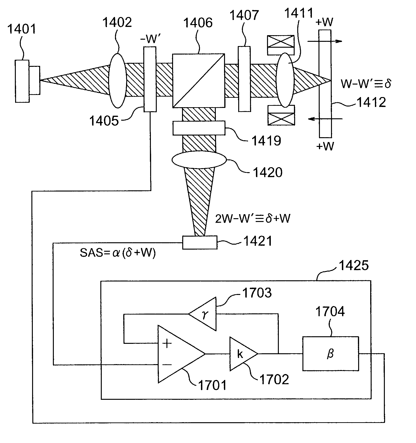
(Embodiment 3)
[0103]FIG. 14 shows an optical disk apparatus according to a further embodiment mode. While light emitted from a semiconductor laser 1401 is collimated by a collimating lens 1402 into parallel light and also an ellipse-shaped beam of an intensity distribution is converted into a circular beam by beam forming prisms 1403 and 1404, spherical aberration is added by a liquid crystal phase compensating element 1405. The liquid crystal phase compensating element 1405 corresponds to such a compensating element that liquid crystal is sandwiched by two base plates on which transparent electrodes are patterned, and a phase of penetration light can be changed by applying an AC voltage to the transparent electrodes. The transparent electrodes are separated into a plurality of regions in correspondence with a wavefront shape of spherical aberration, and voltages are applied in such a manner that phase differences are lowered in the respective regions. The light which has passed thr...
PUM
| Property | Measurement | Unit |
|---|---|---|
| wavelength | aaaaa | aaaaa |
| thickness | aaaaa | aaaaa |
| luminous diameter | aaaaa | aaaaa |
Abstract
Description
Claims
Application Information