

Liquid crystal display device and polarization plate
a technology of liquid crystal display and polarization plate, which is applied in the direction of optics, instruments, optical elements, etc., can solve the problems of the insufficient display of the improvement of the white luminance contributed to the reflection and polarization sheet, so as to suppress linearly polarized light obtained, suppress linearly polarized light, and improve the effect of white luminance in an obliqu
- Summary
- Abstract
- Description
- Claims
- Application Information
AI Technical Summary
Benefits of technology
Problems solved by technology
Method used
Image

Examples
embodiment 1
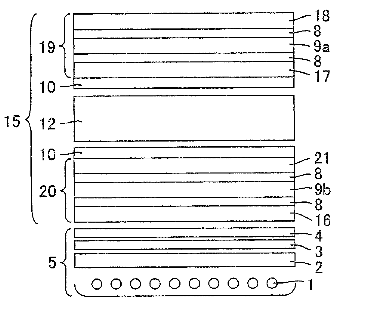
[0083]FIG. 1 is a cross-sectional view schematically showing a configuration of a liquid crystal display device in accordance with Embodiment 1.
[0084]The liquid crystal display device of the present Embodiment is composed of a backlight system 5 and a liquid crystal display panel 15, as shown in FIG. 1. The backlight system 5 is composed of cold-cathode fluorescent tubes (light sources) 1, a diffusion plate 2 (optical member capable of diffusing a light beam by a scattering factor included thereinside), a diffusion sheet 3 (optical member capable of diffusing a light beam by its surface roughness), and a reflection and polarization sheet 4, stacked in this order from the back face side to the front surface side. The liquid crystal display panel 15 is composed of a front polarization plate 19 (observation-side polarization plate) and a back polarization plate 20 (backlight-side polarization plate) that are attached to surfaces of a liquid crystal cell 12 with a cohesive material 10 t...
example 1
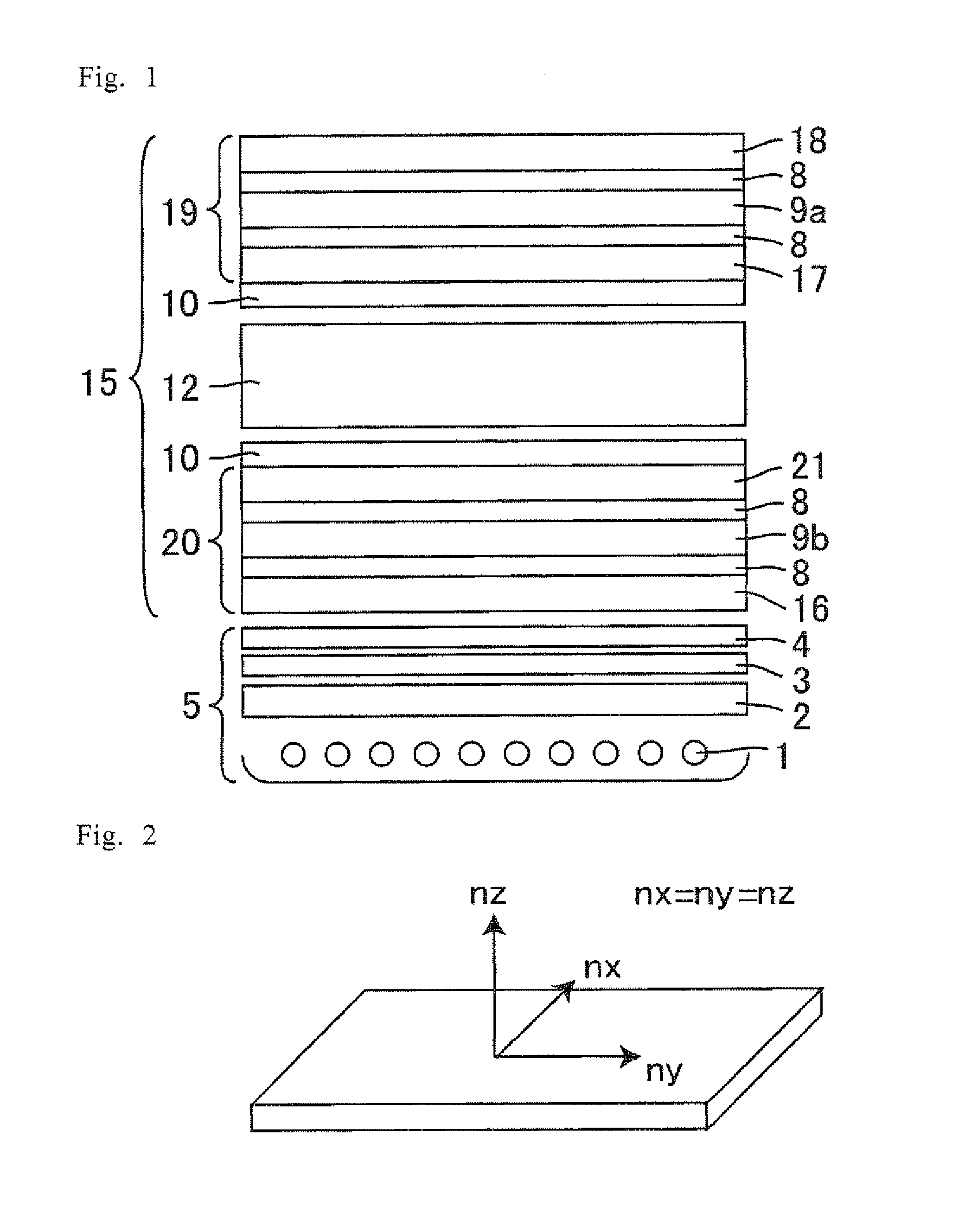
Production of Isotropic Film
[0115]In a pressure-resistant reactor the inside of which was dried and substituted with nitrogen, tetrahydrofuran 500 ml as a solvent, and sec-butyllithium 0.58 mmol as a polarization catalyst, were added. Then, 2-vinyl naphthalene 30 g was added thereto, and a polymerization reaction was allowed to proceed at 30° C. for 2 hours. After completion of the polymerization reaction, the polymerization liquid 1 ml was sampled and charged into a large amount of methanol. As a result, poly(2-vinylnaphthalene) was obtained.
[0116]Then, to the pressure-resistant reactor, isoprene 1.58 g was added after the polarization reaction, and a polymerization reaction was allowed to proceed at 30° C. for 2 hours. As a result, a 2-vinylnaphthalene-isoprene block copolymer was obtained. Then, to the pressure-resistant reactor, dibromo butane 0.1 g was added and a coupling reaction was allowed to proceed at 30° C. for 3 hours. Into the polymerization liquid, a larger amount of ...
example 2
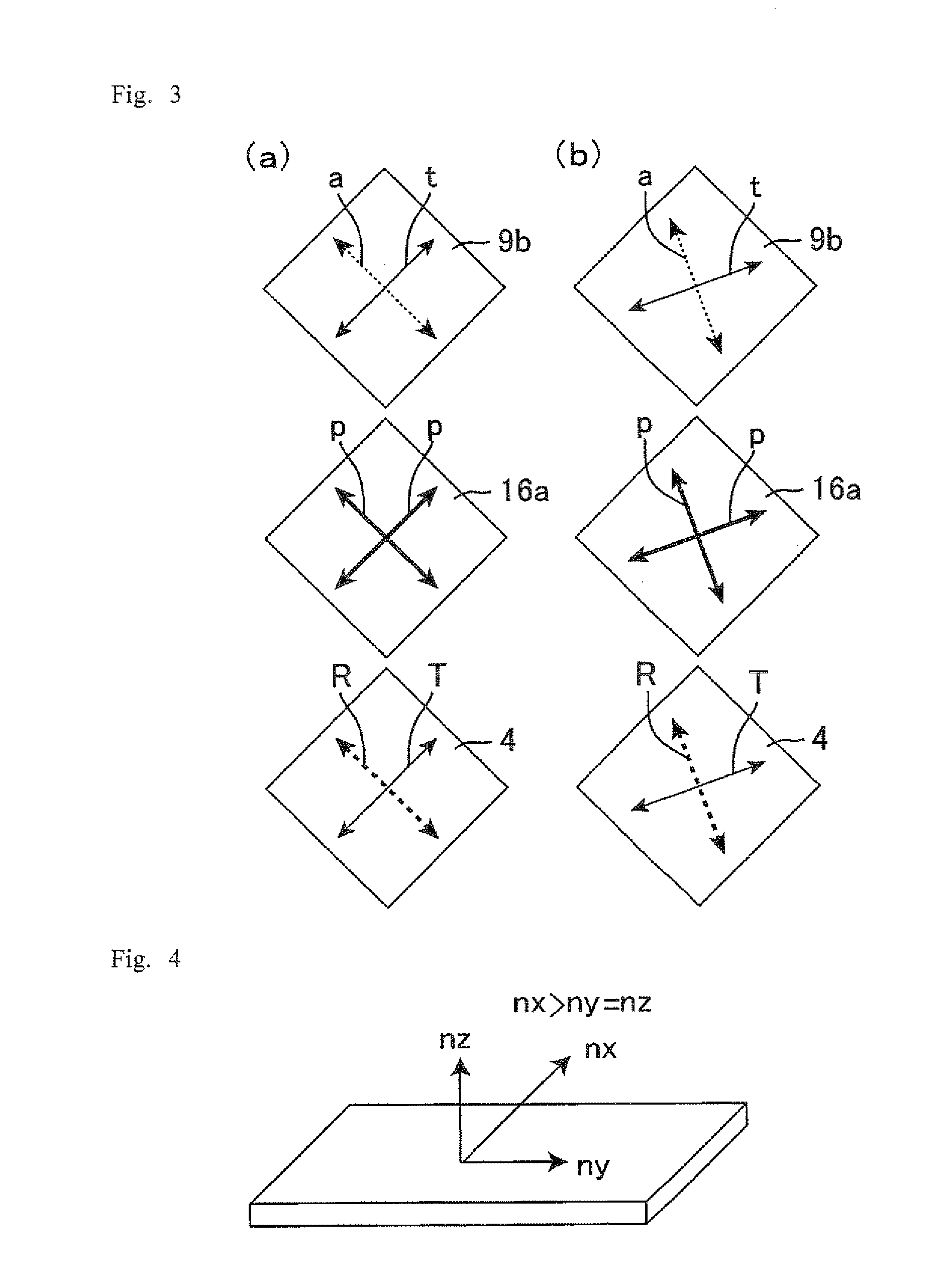
Production of Positive A-Plate
[0120]A norbornene resin that is an amorphous thermoplastic resin (trade name: ZEONOR, product of ZEON CORPORATION) was fed into a T-die extruder, and melt-extruded onto a chill roll at a melting temperature of 230° C. and at a take-up speed of 20 m / min to prepare a Zeonor film. This film was uniaxially stretched through zones of a preliminary heating temperature of 100° C., a stretching temperature of 161° C., and a cooling temperature of 100° C. with a roll longitudinal uniaxial stretching apparatus. Thus-obtained A-plate had a retardation Re of 100 nm and a retardation Rth of 50 nm. The prepared A-plate was attached, as the first protective film, to the one-TAC-including polarization plate (the back face of the back polarizer) produced in the same manner as in Embodiment 1, with a cohesive material therebetween, in such a way that a phase delay axis of the A-plate was parallel to an absorption axis of the back polarizer.
PUM
| Property | Measurement | Unit |
|---|---|---|
| thickness | aaaaa | aaaaa |
| thickness | aaaaa | aaaaa |
| thickness | aaaaa | aaaaa |
Abstract
Description
Claims
Application Information