Exhaust gas purifying system and exhaust gas purifying method

a technology of exhaust gas purification system and purification method, which is applied in the direction of exhaust treatment electric control, electrical control, separation process, etc., can solve the problems of defective regeneration, difficult to hold the temperature of the filter stably in the temperature region, and inability to control the filter temperature, so as to prevent the fusion of the filter and let the pm burn efficiently. , the control logic is very simpl

Inactive Publication Date: 2006-03-21
MITSUBISHI FUSO TRUCK AND BUS CORPORATION
View PDF7 Cites 40 Cited by
  • Summary
  • Abstract
  • Description
  • Claims
  • Application Information

AI Technical Summary

Benefits of technology

[0033]By executing a simple feedback control it is possible to stabilize the filter temperature irrespective of an engine operating condition and the atmospheric temperature and hence there accrues an advantage such that not only it is possible to prevent fusion of the filter but also it is possible to let PM burn efficiently. Besides, after the start of forced regeneration, the filter temperature can be raised rapidly up to a target temperature.
[0034]Since the second additional fuel injection quantit...

Problems solved by technology

According to the technique disclosed in the above literature, the amount of the first additional fuel to be injected is changed according to the filter temperature, but with such a method, it is difficult to hold the filter temperature stably in the temperature region (600° C. and thereabouts) in which the PM burns most efficiently.
It is the second additional fuel quantity that exerts a great influence on the filter temperature, but according to the technique disclosed in the above patent literature it is impossible to control the fil...

Method used


Image

  • Exhaust gas purifying system and exhaust gas purifying method
  • Exhaust gas purifying system and exhaust gas purifying method
  • Exhaust gas purifying system and exhaust gas purifying method

Examples


Embodiment Construction

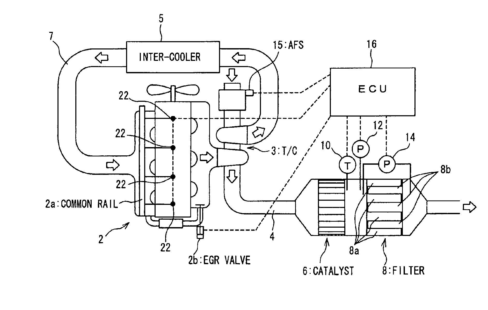
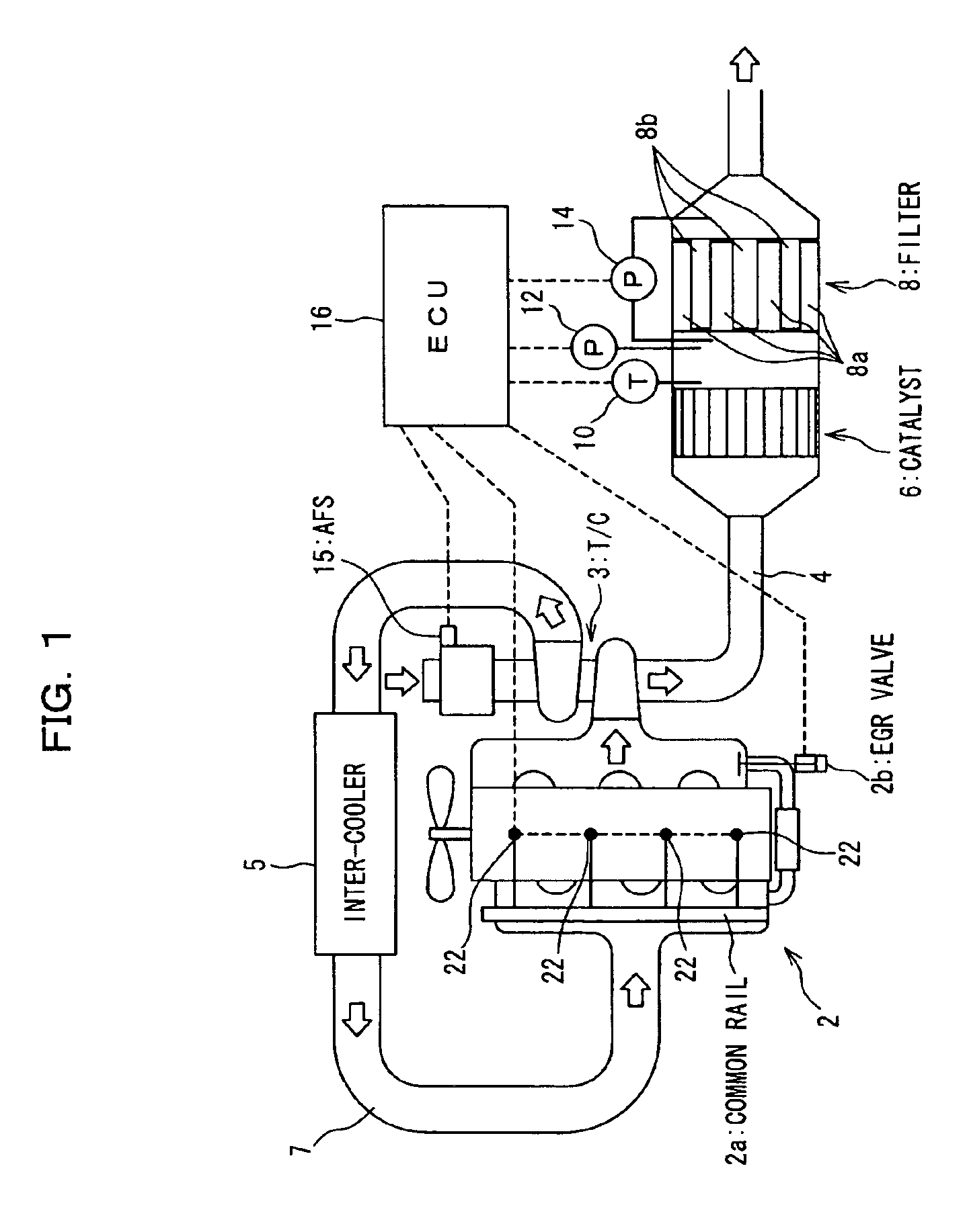
[0042]An exhaust gas purifying system according to an embodiment of the present invention will be described with reference to the accompanying drawings, in which FIG. 1 is a schematic diagram showing an entire construction of the exhaust gas purifying system. In this embodiment, an engine 2 is a diesel engine using gas oil (HC) as fuel. The engine 2 is provided with a common rail type fuel injection system wherein fuel is once stored in a high pressure storage chamber (common rail) 2a which is common to plural cylinders and is then injected.

[0043]In an exhaust passage 4 of the engine 2, an oxidation catalyst (hereinafter referred to simply as “catalyst”) 6 and a diesel particulate filter (simply “filter” hereinafter) 8 are disposed in this order from an upstream side of an exhaust gas flow. Further, a turbocharger 3 is disposed in the exhaust passage 4 and an inter-cooler 5 is disposed in an intake passage 7.

[0044]Though not shown in detail, the whole of the filter 8 is formed of a ...


PUM

PropertyMeasurementUnit
Temperatureaaaaaaaaaa
Timeaaaaaaaaaa
Pressureaaaaaaaaaa

Abstract

In regenerating a filter there are performed a first additional fuel injection involving additional injection of fuel into a cylinder after a main fuel injection in an engine to raise the temperature of an oxidation catalyst and a second additional fuel injection involving fuel injection after the first additional fuel injection to supply the oxidation catalyst with the fuel, a second additional fuel injection quantity is set in accordance with an engine speed and an engine load and is changed in accordance with an outlet temperature of the oxidation catalyst.

Description

BACKGROUND OF THE INVENTION[0001](1) Field of the Invention[0002]The present invention relates to an exhaust gas purifying system and an exhaust gas purifying method both suitable for use particularly in a diesel engine.[0003](2) Description of Related Art[0004]Heretofore, there has been known a technique wherein an oxidation catalyst and a particulate filter (hereinafter referred to simply as “filter”) are disposed in an exhaust passage of a diesel engine, allowing a particulate matter (PM) contained in exhaust gas to be deposited on the filter, and the PM thus deposited on the filter is burnt to regenerate the filter continuously.[0005]In the exhaust gas purifying system constructed as above, NO contained in exhaust gas is oxidized in the oxidation catalyst to produce NO2, then the NO2 and the PM on the filter are reacted with each other, allowing the PM to burn (be oxidized) to regenerate the filter continuously. NO2 exhibits a high function as an oxidizing agent in comparison wi...

Claims


Application Information

Patent Timeline
IPC IPC(8): F01N3/00F02D45/00B01D46/42F01N3/02F01N3/023F01N3/025F01N3/029F01N3/24F01N3/36F01N9/00F01N13/02F02B29/04F02B37/00F02D41/02F02D41/04F02D41/38F02D41/40F02M25/07
CPCF02D41/029F01N13/0097F02D41/405F01N2430/085F02B29/0406F02B37/00F02D41/402F02D2200/0802F02D2200/0812F02M25/0707Y02T10/44F02M26/05Y02T10/40A47K3/004A47K3/022
Inventor HIRANUMA, SATOSHITAKEDA, YOSHINAKAKAWATANI, TORUDOUMEKI, REIKO
Owner MITSUBISHI FUSO TRUCK AND BUS CORPORATION
Why Eureka
Try Eureka