Method and apparatus for inline measurement of material removal during a polishing or grinding process

a technology of material removal and polishing process, which is applied in the direction of grinding/polishing apparatus, grinding machine components, grinding/polishing machines, etc., can solve the problems of limited polishing speed, manual and time-consuming investigation, and limited mechanical set-up and flexibility of the polishing pad, so as to save time in the process

Inactive Publication Date: 2006-03-21
STRUERS
View PDF14 Cites 12 Cited by
  • Summary
  • Abstract
  • Description
  • Claims
  • Application Information

AI Technical Summary

Benefits of technology

[0015]The present invention provides a system for inline measurement of material removal automatically without interference from vibration of the grinder or polisher. Basically, to perform such a measurement access is needed to a well-defined bottom surface of the sample where the polishing action takes place, and a well-defined reference mark preferably on either the sample or the sample holder. Furthermore, the frequency of measurement of the relative position of these two points must be much higher than the vibration of the equipment. This is achieved by sweeping the sample to pass over the rim of the grinding / polishing pad, thereby allowing access to both the top and bottom of the sample. This method will yield a perfect result despite misalignment of the sample during mounting.
[0025]The size of the sample or specimen may vary considerably. Typically, the specimens have a circular cross section but any geometry may be used as long as the part of the specimen constituting the bottom surface and used for the measurement of the aforementioned distance has sufficient size for the measurement to be made. The specimen should preferably be at least approx. 1 cm over the rim of the polishing or grinding pad when the measurement takes place. However, by carefully positioning the measurement system, smaller amounts or areas of sample can be acceptable.
[0031]The apparatus may further comprise a sweeping mechanism to facilitate the use of a larger fraction of the polishing pad as well as reduce the likelihood of half moon formation on the sample. Furthermore, sweeping of the sample leads to a more even scratch pattern on the sample. The sample may be swept along a line for example in radial direction on the polishing or grinding pad or along a fraction of a circular path. Anyway, the sample must pass the rim of the polishing or grinding pad when the aforementioned distance is measured.
[0049]By use of the method according to the invention it is possible to grind or polish a sample with very high precision.
[0052]In a preferred embodiment a planar surface which is substantially parallel to the surface of the grinding or polishing pad is used as reference mark, preferably the planar surface is the upper part of the sample and / or the sample holder. In this embodiment the reference mark can be established in an easy and uncomplicated way.

Problems solved by technology

However, this technique is limited by the precision of the mechanical set-up and the flexibility of the polishing pad.
The microscope may be built into the polishing apparatus, but the investigation is manual and time consuming.
However, the measuring system needs to be manually set up for each type of sample and the polishing speed is limited.
This requires specially prepared polishing pads and is rather complicated to control.
Furthermore, the measurement system uses diffraction of white light for the determination of the film thickness, which is not suitable for non-transparent materials.
To realise high precision the system must be highly mechanically stiff, which is expensive and difficult to achieve for lab-size equipment.
Otherwise the vibration of the polishing system during operation together with the flexibility of the polishing pad reduces the precision of these methods.

Method used


Image

  • Method and apparatus for inline measurement of material removal during a polishing or grinding process
  • Method and apparatus for inline measurement of material removal during a polishing or grinding process
  • Method and apparatus for inline measurement of material removal during a polishing or grinding process

Examples


example 1

Optimization of Self-timing Parameters

[0108]To prove the feasibility of the invention an experimental set-up consisting of a rebuilt Labopol-6, Struers and a laser scanning micrometer (LS-5041, Keyence) was built. The LS-5041 was connected to a personal computer by RS-232 and controlled by a LS-5001 unit via the standard controller software from Keyence. The LS-5041 was run in self-timing mode during this experiment.

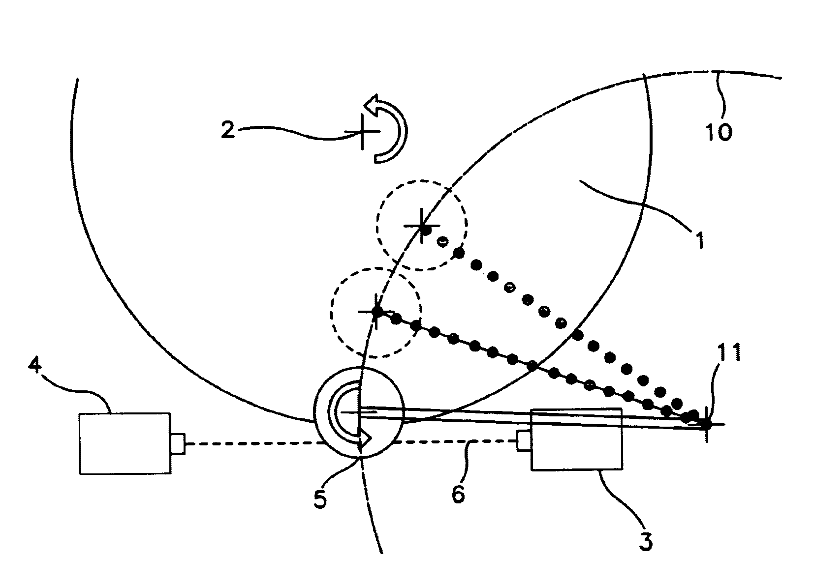
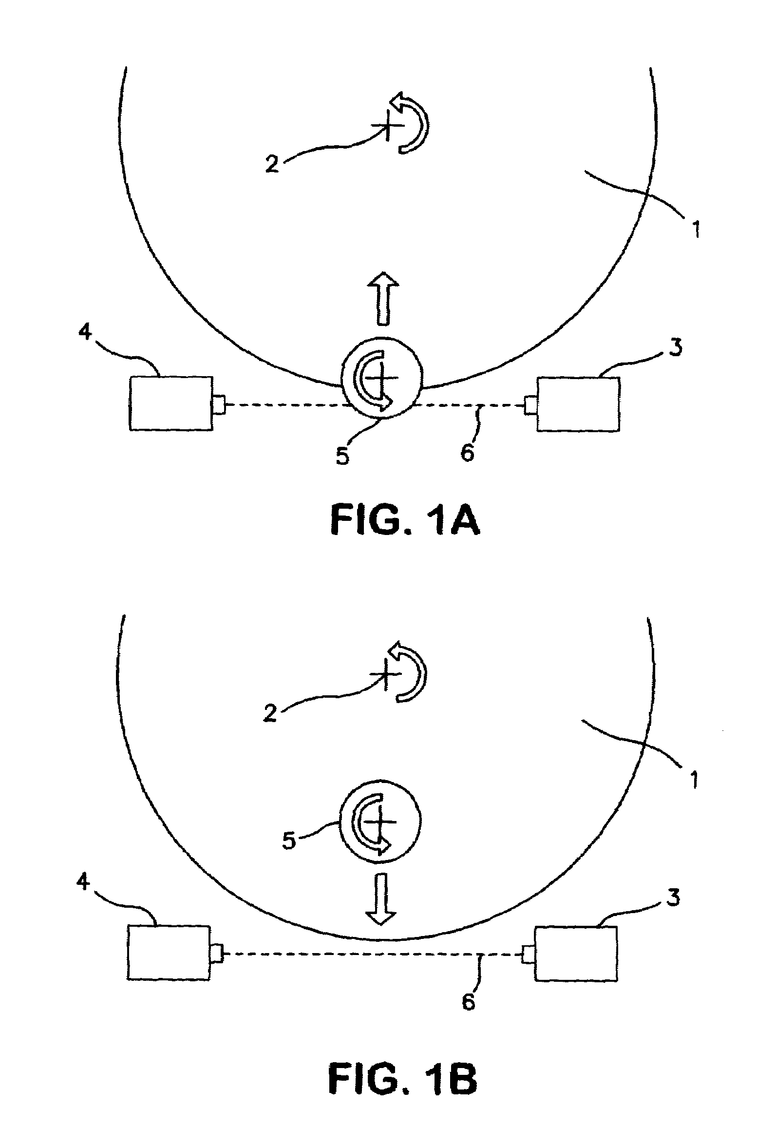
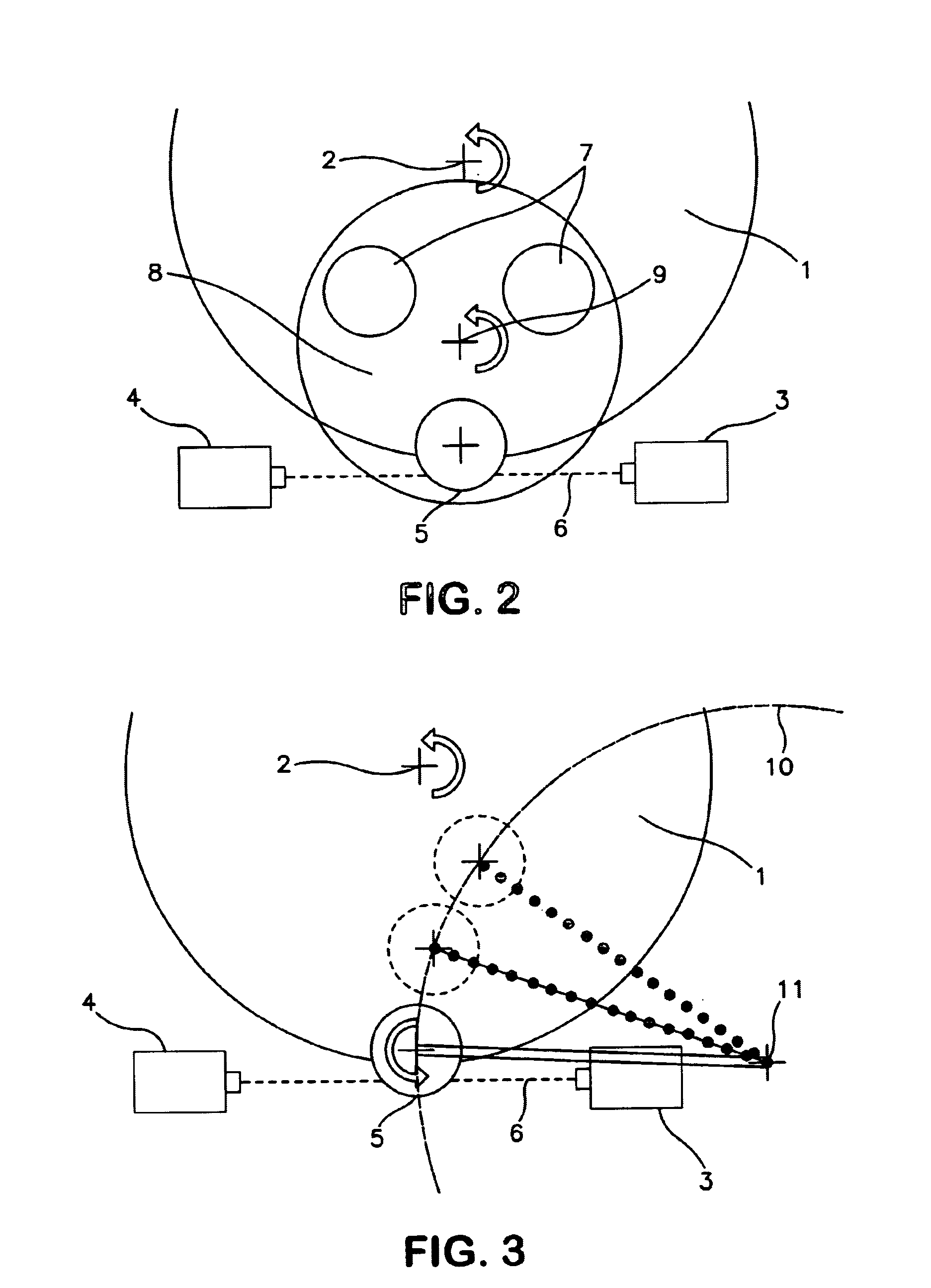
[0109]To simulate the polishing situation the set-up sketched in FIG. 7 was deployed. In FIG. 7A the set-up is seen from the top. The test sample (5) was a steel cylinder on the end of a moving arm (41). The moving arm was connected to a metal foot (40) by a rotatable metal cylinder (42). In FIG. 7B the same set-up is seen from the side. The laser receiver and the laser beam ((4) and (6), respectively, in e.g. FIG. 7A) are hidden behind the laser emitter (3).

[0110]The pause from the laser beam lattice was broken until the beginning of the measurement was varied between 1...

example 2

Sensitivity Towards Mechanical Vibration of the Experimental Set-up

[0113]The sensitivity towards mechanical vibration of the system is crucial for the feasibility of the system since it is an inline system.

[0114]The sensitivity towards mechanical vibration of the system was tested using a LS-5041, Keyence, placed on a Labopol-6, Struers. A steel cylinder with parallel end faces was placed in the measuring field of the LS-5041. The sample height was measured with the Labopol-6 deactivated and with the Labopol-6 running with 100 rpm.

[0115]The LS-5041 was run in normal mode meaning that the height of the cylinder was measured continuously.

[0116]In FIG. 8 screen prints of the results are shown. The results show that the measured height of the sample is 18.873 mm (without vibration, FIG. 7A) and 18.874 mm (with vibration, FIG. 7B), respectively. In both cases the measurement varies approximately ±2 μm. It is noted that the measured height does not vary significantly. Furthermore, the var...

example 3

Sensitivity of Measurement Towards Water

[0117]Grinding processes are often cooled by excessive amounts of water. The sensitivity towards both airborne water droplets as well as drops of water on the laser transducer and receiver window was therefore investigated.

[0118]The LS-5041 may be programmed to take into account only bulk items and airborne water droplets which obstruct the laser beam and will therefore not in general contribute to the measured height. If a droplet by chance is placed immediately above or below the shadow of the sample, it will contribute to the measured height but since the result to be carried to the controller will be an average over time the contribution from a droplet drifting in the air will not be significant for moderate amounts of water droplets.

[0119]Drops of water on the laser glass will act as an optical lens and hence divert the direction of the monochromatic laser beam. Since the laser receiver will only accept beams coming in a straight line fro...


PUM


Abstract

Apparatus for inline measurement of material removal during a polishing or grinding process including:a. a substantially circular rotatable grinding or polishing pad; andb. a sample holder; andc. a sample with a top, a bottom and one or more side surfaces;the sample holder being arranged to hold the bottom surface of the sample in contact with the pad and the sample holder being connected to a moving device to move the sample to a position at least partially over the rim of the pad, during at least a part of the process, the apparatus also including a detecting device for sampling the distances between a reference mark and a target area in the sample and a plane defined by the bottom surface of the sample during the process.

Description

CROSS REFERENCE TO RELATED APPLICATION[0001]This application is a continuation-in-part of PCT / DK02 / 00610, filed 20 Sep. 2002, the priority of which is claimed.FIELD OF THE INVENTION[0002]The invention relates to materialographic grinders and polishers and more particularly to inline measurement of material removal on rotary grinders or polishers for preparation of samples to micron or submicron precision. Inline measurement means that the measurement is performed during / simultaneously with the grinding or polishing process.BACKGROUND OF THE INVENTION[0003]Materialographic grinders and polishers are used intensively for preparation of raw material and for preparation of samples to microstructural analysis. For example submicron precision polishing is used for preparation of silicon wafers which are useful for chip fabrication. Automated grinding is widely used as a shaping process of solid materials, for example for final shaping of sintered advanced ceramic components and various me...

Claims


Application Information

Patent Timeline
Patent Type & Authority Patents(United States)
IPC IPC(8): B24B49/00B24B37/04B24B49/12
CPCB24B49/12B24B37/04
Inventor HANSEN, JESPER ROMER
Owner STRUERS
Why Eureka
Try Eureka