Semiconductor device and manufacturing method thereof

a semiconductor device and manufacturing method technology, applied in semiconductor devices, instruments, electrical apparatus, etc., can solve the problems of reducing the accumulated capacity of capacitors, lowering the contrast of image displays, and high off current, so as to improve the operation performance and reliability of semiconductor devices, prevent degradation, and relieve the effect of electric field

Inactive Publication Date: 2006-03-21
SEMICON ENERGY LAB CO LTD
View PDF41 Cites 51 Cited by
  • Summary
  • Abstract
  • Description
  • Claims
  • Application Information

AI Technical Summary

Benefits of technology

[0019]The present invention enables improvement of the operation performance and the reliability of a semiconductor device by properly using the above stated TFTs over the same substrate.
[0020]A measure is further taken in the structure of the LDD region of an n-channel TFT for preventing the degradation due to hot carrier injection. In other words, the present invention has a characteristic in disposing a concentration gradation in the LDD region between the channel forming region and the drain region so that the concentration of n-type impurity element becomes gradually higher as getting closer to the drain region. This structure calculate upon higher effect of relieving the electric field.
[0021]Further in case of disposing the above stated concentration gradation, the concentration of n-type impurity element included in the proximity of the boundary between a LDD region and the channel forming region of an n-channel TFT becomes lower than the concentration included in the proximity of the boundary between the LDD region and the drain region. A higher effect of relieving electric field is obtained in the similar way.

Problems solved by technology

However, the poly-silicon TFT involves the problem that its OFF current is likely to become high.
It is believed that the main cause is hot carrier injection, and the hot carriers generated by a high electric field in the proximity of the drain presumably invite this degradation.
However, the accumulated capacity of this capacitor decreases gradually due to a leakage current resulting from the OFF current, or the like.
Consequently, the quantity of transmitting rays of light changes, thereby lowering the contrast of image display.
On the contrary, the ordinary LDD structures have a high effect for restricting the OFF current value, but is not resistant to hot carrier injection, as is well known in the art.

Method used


Image

  • Semiconductor device and manufacturing method thereof
  • Semiconductor device and manufacturing method thereof
  • Semiconductor device and manufacturing method thereof

Examples


embodiment 1

[Embodiment 1]

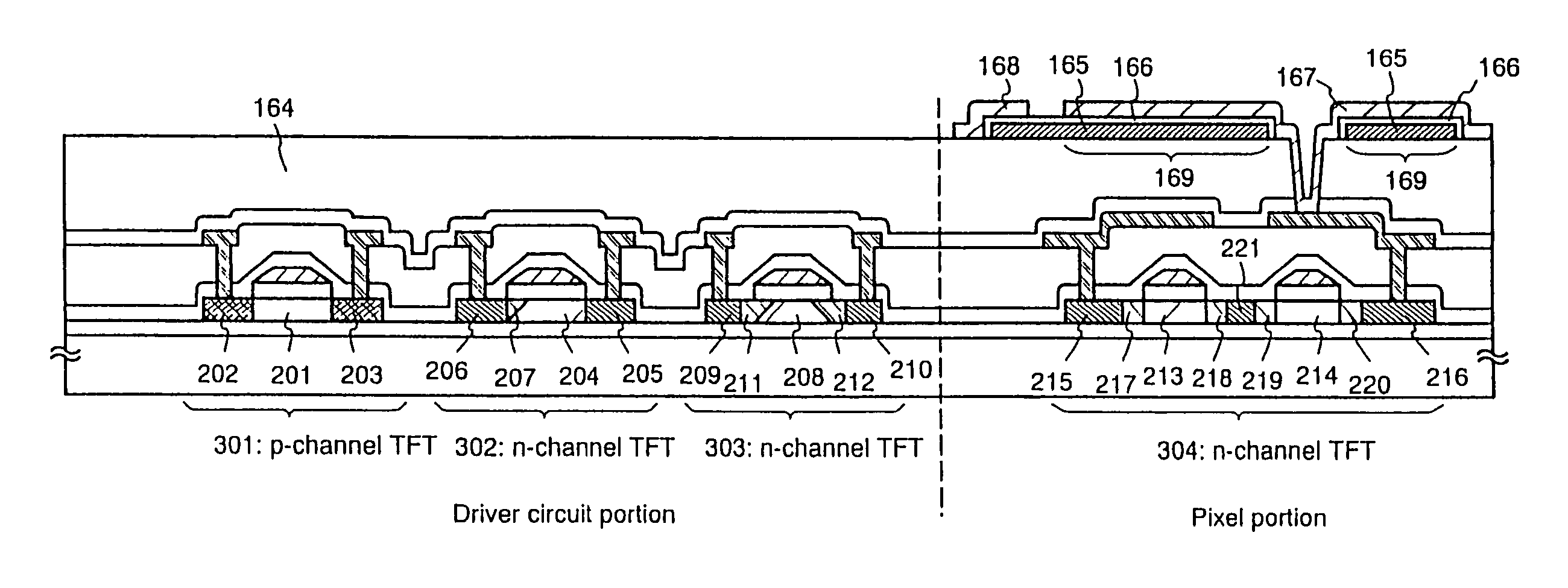
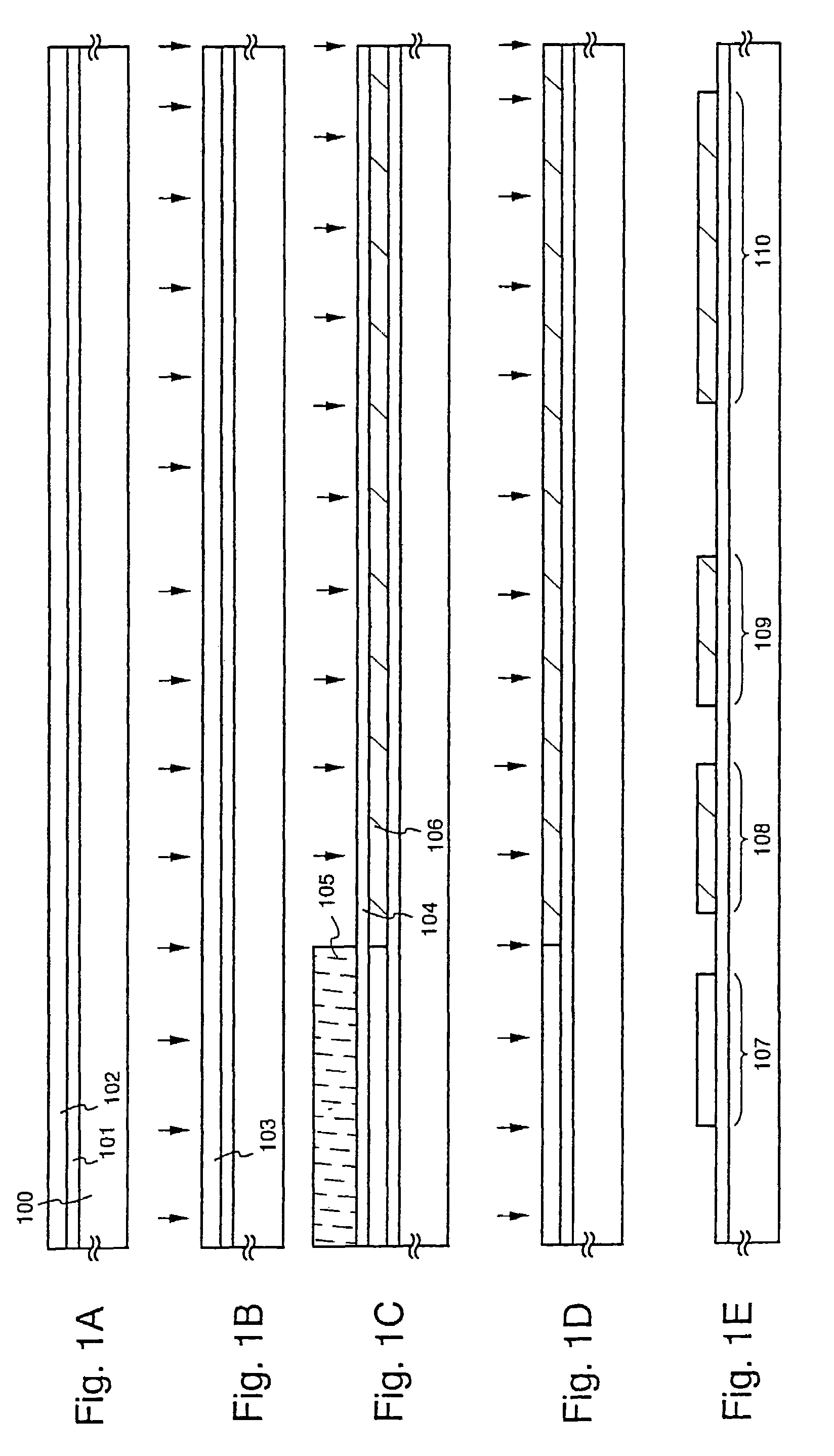
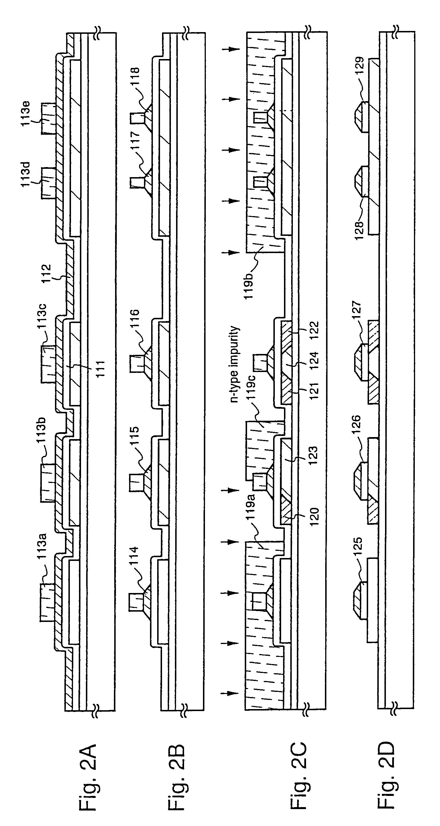
[0044]An embodiment according to the present invention is described by using FIGS. 1A to 4B. A method for fabricating at the same time, TFTs for a pixel section and a driver circuit provided in its peripheral, is described here. Note that a CMOS circuit which is a basic circuit for a shift register and buffer etc., and an n-channel TFT forming a sampling circuit are shown for the driver circuit for the simplicity of explanation.

[0045]In FIG. 1A, it is preferable to use a glass substrate or a quartz substrate for substrate 100. Other than those, a silicon substrate, a metal substrate or a stainless steel substrate having an insulating film formed on the surface thereof may be used. If heat resistivity permits, it is also possible to use a plastic substrate.

[0046]A base film 101 formed from an insulating film comprising silicon (“an insulating film comprising silicon” generically represents a silicon oxide film, a silicon nitride film and a silicon oxynitride film in the...

embodiment 2

[Embodiment 2]

[0136]A process of manufacturing an active matrix type liquid crystal display device from an active matrix substrate is next explained. As shown in FIG. 5, an alignment film 401 is formed for the substrate in the state of FIG. 4B. In the present embodiment, a polyimide film is used for the alignment film. An opposing electrode 403 comprising transparent conductive film and an alignment film 404 are formed on an opposing substrate 402. Color filter or a shielding film may be formed on the opposing substrate if necessary.

[0137]After forming the alignment films, a rubbing process is performed to give the liquid crystal molecules a certain fixed pre-tilt angle, so that they are aligned. The active matrix substrate, on which a pixel section and driver circuits are formed, and the opposing substrate are stuck together through a sealing material, spacers, or a resin film provided by patterning (not shown in the figures) in accordance with a known cell assembly process. A liqu...

embodiment 3

[Embodiment 3]

[0139]FIG. 9 shows an example of circuit structure of the active matrix substrate shown in embodiment 2. The active matrix substrate of embodiment 3 has a image signal driver circuit 801, a scanning signal driver circuit (A) 807, a scanning signal driver circuit (B) 811, a pre-charge circuit 812, and a pixel section 806. Through the Specification, driver circuit is a generic name including image signal driver circuit 801 and a scanning signal driver circuit 807.

[0140]The image signal driver circuit 801 is provided with a shift register circuit 802, a level shifter circuit 803, a buffer circuit 804, and a sampling circuit 805. Further, the scanning signal driver circuit (A) 807 is provided with a shift register circuit 808, a level shifter circuit 809, and a buffer circuit 810. The scanning signal driver circuit (B) 811 has a similar structure.

[0141]The driver voltages for the shift register circuits 802 and 808 is between 5 and 16 V here (typically 10 V), and the struc...


PUM

PropertyMeasurementUnit
taper angleaaaaaaaaaa
thicknessaaaaaaaaaa

Abstract

A semiconductor device having high operating performance and reliability, and a manufacturing method thereof are provided.
An LDD region 207 provided in an n-channel TFT 302 forming a driving circuit enhances the tolerance for hot carrier injection. LDD regions 217–220 provided in an n-channel TFT (pixel TFT) 304 forming a pixel portion greatly contribute to the decrease in the OFF current value. Here, the LDD region of the n-channel TFT of the driving circuit is formed such that the concentration of the n-type impurity element becomes higher as the distance from an adjoining drain region decreases.

Description

[0001]This application is a Division of 10 / 329,405 filed Dec. 27, 2002 (U.S. Pat. No. 6,753,257) which is a Division of 09 / 559,185 filed Apr. 27, 2000 (U.S. Pat. No. 6,534,826).BACKGROUND OF THE INVENTION[0002]1. Field of the Invention[0003]This invention relates to a semiconductor device having a circuit or an element comprising thin film transistors (hereinafter referred to as “TFTs”) on a substrate having an insulating surface, and to a manufacturing method thereof. More specifically, the present invention relates to electro-optical devices (called also “electronic equipments”) typified by a liquid crystal display device including a pixel section (pixel matrix circuit) and driver circuits disposed around the pixel section and formed on the same substrate and, and electrical devices (called also “electronic appliances”) having the electro-optical device mounted thereto. Note that, throughout this specification, the semiconductor device indicates general devices that can function b...

Claims


Application Information

Patent Timeline
Patent Type & Authority Patents(United States)
IPC IPC(8): H01L21/302H01L21/461G02F1/1362H01L21/336H01L21/77H01L21/84H01L27/12H01L27/32H01L29/423H01L29/49H01L29/786
CPCH01L21/2026H01L21/3003H01L29/42384H01L29/66757H01L29/78621H01L27/1255H01L29/4908G02F1/13454H01L27/3244H01L2029/7863H01L29/78645H01L21/02686H01L21/0242H01L21/02683H01L21/02381H01L21/02425H01L21/02488H01L21/02422H01L21/02592H01L21/02532H01L21/02672H01L21/02678H10K59/12H01L21/02675
Inventor YAMAZAKI, SHUNPEI
Owner SEMICON ENERGY LAB CO LTD
Why Eureka
Try Eureka