Electroluminescent devices and method of making transparent cathodes

a technology of electroluminescent devices and cathodes, which is applied in the manufacture of electrode systems, electric discharge tubes/lamps, and discharge tubes luminescent screens, etc., can solve the problems of difficult to achieve reasonable contrast of the image generated by the display, the cathode layer is highly reflective, and the transparent electrode materials such as indium tin oxide (“ito”) cannot be used as cathodes

Inactive Publication Date: 2006-03-21
PICTIVA DISPLAY INT LTD
View PDF17 Cites 23 Cited by
  • Summary
  • Abstract
  • Description
  • Claims
  • Application Information

AI Technical Summary

Problems solved by technology

The conductive layer has to be thick enough to be adequately conductive, however, the thickness providing adequate conductivity results in the cathode layer being highly reflective.
Transparent electrode materials such as indium tin oxide (“ITO”) cannot be used as a cathode because it is typically deposited in a manner that causes damage to the organic layer within the OLED and also because it does not have a low work function.
In an OLED display, it is difficult to achieve reasonable contrast of the image generated by the display when ambient light emitted from an external bright light source, such as the sun, is reflected from the cathode.
One disadvantage of using circular polarizers is that about sixty percent of the light emitted by the OLED is absorbed by the circular polarizer and never reaches the viewer.
This absorption results in the necessity to drive the OLED at higher brightness considerably decreasing its life and increasing its power consumption.
The increased power consumption is detrimental for battery-operated devices.
Another disadvantage is that the emitted light that reaches the viewer is linearly polarized by the components of the circular polarizer.
A further disadvantage is the processing difficulty of adhering the circular polarizer to the viewing surface of the OLED.
Another disadvantage is that the circular polarizer, typically a polymeric film, mounted onto the viewing surface presents additional failure points in the overall OLED module, particularly under high heat and humidity conditions.
The disadvantage of this approach is that in implementing it, the processing is difficult as the thicknesses of the one or more additional layers have to be exact in order to achieve the destructive interference and the processing of the OLED involves the deposition of additional layers.

Method used


Image

  • Electroluminescent devices and method of making transparent cathodes
  • Electroluminescent devices and method of making transparent cathodes
  • Electroluminescent devices and method of making transparent cathodes

Examples


second embodiment

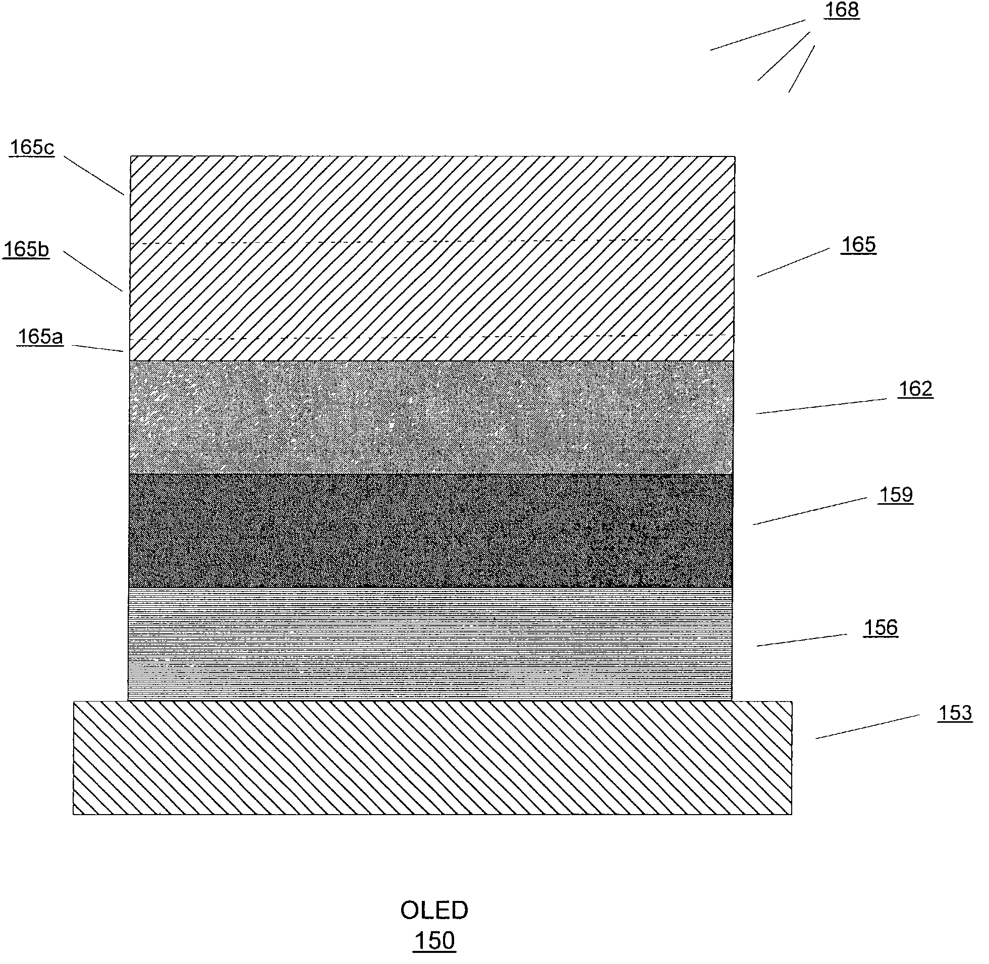
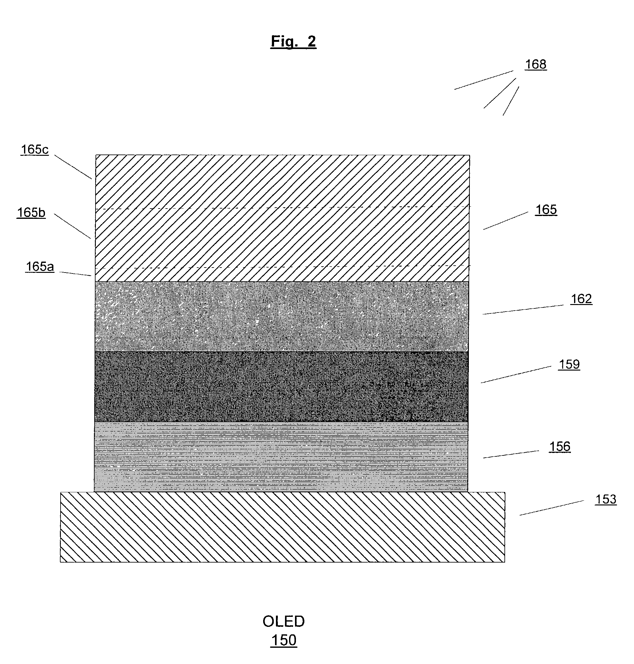
[0046]FIG. 8 shows an OLED 177 according to the present invention. In FIG 8, a barrier layer 165d is deposited on the electron injecting layer 165a and the conductive layer 165b is deposited on the barrier layer 165d. The barrier layer 165d minimizes or eliminates reaction between the electron injecting layer and the conductive layer. Reaction between the electron injecting layer and the conductive layer may reduce charge injection from the conductive layer to the emissive polymer layer thus adversely affecting luminance and efficiency of the OLED. In one configuration, the barrier layer 165d is comprised of a conductive layer such as a gold layer or an aluminum layer. The barrier layer 165d is thick enough to minimize or eliminate reaction between the electron injecting layer and the conductive layer but not too thick that it not substantially transparent. In this embodiment, the thickness of the barrier layer 165d varies from about 0.1 nm to about 20 nm and preferably is from abou...

third embodiment

[0047]FIG. 9 shows an OLED 210 according to the present invention. In this embodiment, a capping layer 171 is vacuum-deposited onto a top electrode such as the cathode layer 165 to improve, for example, the conductivity and lifetime of the OLED 210. The capping layer 171 provides higher luminance and efficiency due in part to the light reflection from the capping layer and also the higher current injection into the emissive polymer layer 162. In this embodiment, the capping layer 171 is comprised of a metal such as, for example, aluminum, silver, magnesium, or an alloy thereof. In other embodiments, the capping layer 171 is comprised of a transparent and conductive material such as ITO, zinc oxide, tin oxide, and zinc sulfide that is deposited by sputtering techniques. The capping layer 171 may also be comprised of black light absorbing conductive organic or inorganic materials. The range of thickness for the capping layer 171 is from about 50 nm to about 10,000 nm; preferably is fr...


PUM


Abstract

An embodiment of the present invention pertains to an electrode that is substantially transparent and conductive and that is incorporated within an organic electronic device. This electrode includes a first layer and a second layer that is on the first layer. The electrode optionally includes a third layer on the second layer. The first layer, the second layer, and the third layer are exposed to a medium and reactions between various combinations of the first layer, the second layer, the third layer, and the medium produce the substantially transparent and conductive electrode.

Description

BACKGROUND OF THE INVENTION[0001]1. Field of the Invention[0002]This invention relates generally to an organic electronic device, in particular, to an electrode that is substantially transparent and conductive and incorporated in the organic electronic device.[0003]2. Description of the Related Art[0004]Organic electronic devices include those which convert electrical energy into optical energy, or vice versa, as well as those that detect optical signals through electronic processes. Such organic electronic devices include OLEDs, solar cells, phototransistors, photodetectors, lasers, and opto-couplers. Such devices typically include a pair of electrodes (e.g., an anode and a cathode) with at least one charge-carrying layer between the electrodes. Depending on the function of the device, the charge-carrying layer or layers may be comprised of a material or materials that are electroluminescent when a voltage is applied across the device or the layer or layers may form a heterojunctio...

Claims


Application Information

Patent Timeline
Patent Type & Authority Patents(United States)
IPC IPC(8): H05B33/00H01J9/14H01L27/32H01L51/50H01L51/52H05B33/04H05B33/10H05B33/28
CPCH01L51/5234H05B33/28H05B33/10H01L51/5281H01L27/3209H01L2251/5315H10K59/32H10K50/828H10K50/86H10K2102/3026
Inventor STEGAMAT, REZACUMPSTON, BRIAN H.
Owner PICTIVA DISPLAY INT LTD
Why Eureka
Try Eureka