Delay-locked loop device capable of anti-false-locking

a loop device and anti-false locking technology, applied in the direction of oscillation comparator circuits, automatic control of pulses, instruments, etc., can solve the problems of limited effect of prior art dll devices b>10/b>, limit the minimum lock range of dll devices b>, and cannot limit the lock range limitation

Active Publication Date: 2006-03-21
FARADAY TECH CORP
View PDF6 Cites 18 Cited by
  • Summary
  • Abstract
  • Description
  • Claims
  • Application Information

AI Technical Summary

Benefits of technology

[0011]According to the claimed invention, a delay-locked loop device capable of anti-false-locking includes a voltage control delay circuit including a plurality of delay units in a series for generating a delayed phase according to a reference phase and a control voltage; a phase detector coupling to the voltage control delay circuit for generating a control signal according to a lock indication signal, the reference phase, and the delayed phase; a charge pump coupling to the phase detector for generating the control voltage to the voltage control delay circuit according to the control signal; and a lock detector coupling to the voltage control delay circuit for generating the lock indication signal for the phase detector according to output phases of each delay unit of the voltage con

Problems solved by technology

However, the operations of the prior art DLL device 10 are limited by effects of harmonic lock and stuck lock.
Moreover, the process of reaching lock also limits the minimum lock range of the DLL device 10 as Tmin.
Nevertheless, the limitations of the lock ranges cannot conform to some applications, and may cause false lock.
However, in high-precision applications, the precise delayed phase Fdl is needed.
Moreover, each unit (or block) i

Method used


Image

  • Delay-locked loop device capable of anti-false-locking
  • Delay-locked loop device capable of anti-false-locking
  • Delay-locked loop device capable of anti-false-locking

Examples


Embodiment Construction

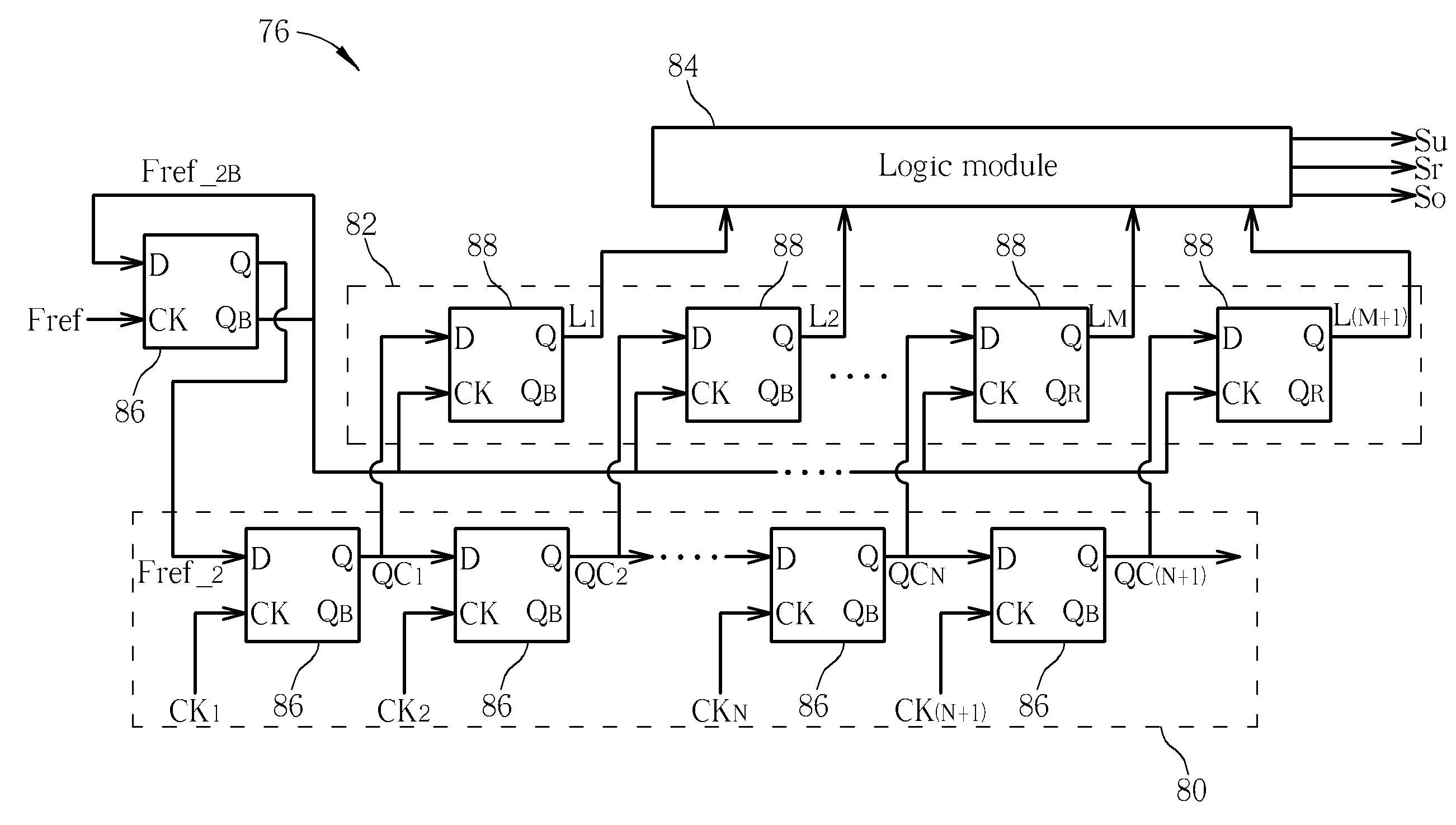
[0024]Please refer to FIG. 8, which illustrates a schematic diagram of a DLL device 60 capable of anti-false-locking in accordance with the present invention. The DLL device 60 includes a phase detector 62, a charge pump 64, a loop filter 66, a voltage control delay circuit 68, a reference-phase generator 70, and a lock detector 76. The voltage control delay circuit 68 includes a plurality of delay units 72 for outputting a delayed phase Fde from the last delay unit 72 to the phase detector 62. The DLL device 60 forms a lock loop 74 according to a lock indication signal Spl provided by the lock detector 76, including an under signal Su, a right signal Sr, and an over signal So. As to a configuration of the lock detector 76, please refer to FIG. 9. In FIG. 9, the lock detector 76 includes a frequency divider 78, a first shift register set 80, a second shift register set 82, and a logic module 84. The first shift register set 80 includes N pieces of D flip-flops 86, while the second s...


PUM


Abstract

A delay-locked loop device capable of anti-false-locking includes a voltage control delay circuit including a plurality of delay units in a series for generating a delayed phase according to a reference phase and a control voltage; a phase detector coupling to the voltage control delay circuit for generating a control signal according to a lock indication signal, the reference phase, and the delayed phase; a charge pump coupling to the phase detector for generating the control voltage to the voltage control delay circuit according to the control signal; and a lock detector coupling to the voltage control delay circuit for generating the lock indication signal for the phase detector according to output phases of each delay unit of the voltage control delay circuit.

Description

BACKGROUND OF INVENTION[0001]1. Field of the Invention[0002]The present invention relates to a delay-locked loop device, and more particularly, a delay-locked loop device capable of anti-false-locking and increasing the operating range with a lock detector.[0003]2. Description of the Prior Art[0004]Digital integrated circuits have been highly developed. Personal computers, mobile phones, digital watches, and calculators, for example, are applications of digital integrated circuits. With high-speed, microminiaturized, and multi-function developments, a complex digital integrated circuit often includes a plurality of units. The units delay a reference timer with different degrees, so a delay-locked loop (DLL) device is need for maintaining synchronization of the digital integrated circuit.[0005]Please refer to FIG. 1, which illustrates a schematic diagram of a prior art DLL device 10. The DLL device 10 includes a phase detector 12, a charge pump 14, a loop filter 16, a voltage control...

Claims


Application Information

Patent Timeline
IPC IPC(8): H03L7/06
CPCH03L7/0812H03L7/095Y10S331/02H03L7/0816
Inventor YU, MING-SHIHTSENG, YUH-KUANG
Owner FARADAY TECH CORP
Why Eureka
Try Eureka