
Regenerative fume-incinerator with on-line burn-out and wash-down system

a regenerative fume incinerator and online technology, applied in the direction of cleaning with liquids, furnaces, combustion types, etc., can solve the problems of not being useful in removing non-combustible deposited matter from prone to fouling, and relatively dense heat sink media in the regenerative heat exchanger of regenerative fume incinerators

Inactive Publication Date: 2006-03-28
PRO ENVIRONMENTAL
View PDF13 Cites 15 Cited by
  • Summary
  • Abstract
  • Description
  • Claims
  • Application Information

AI Technical Summary

Benefits of technology

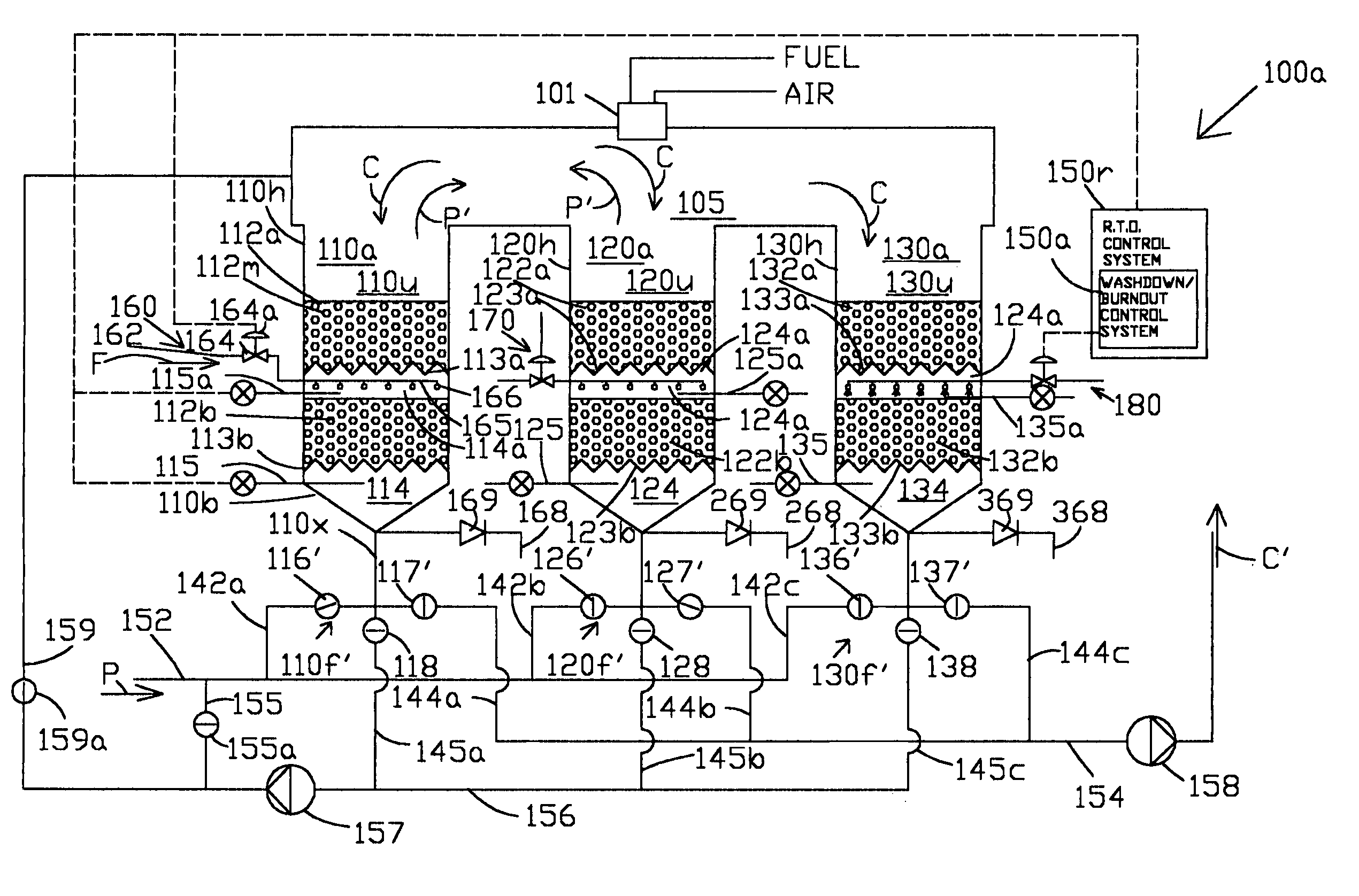
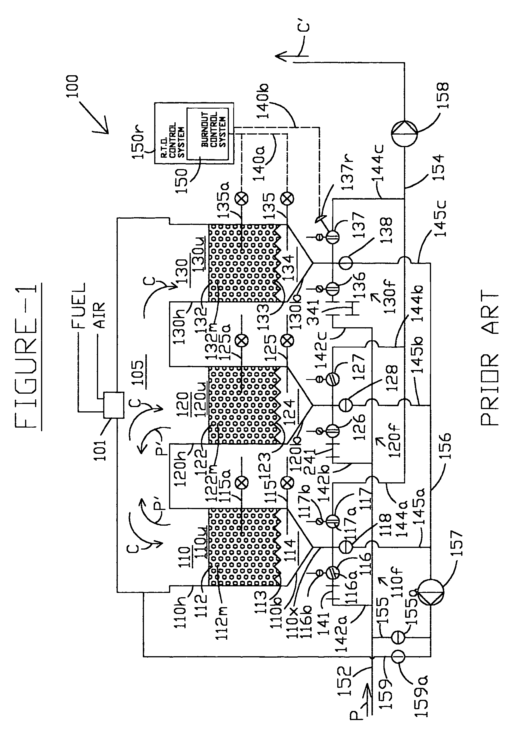
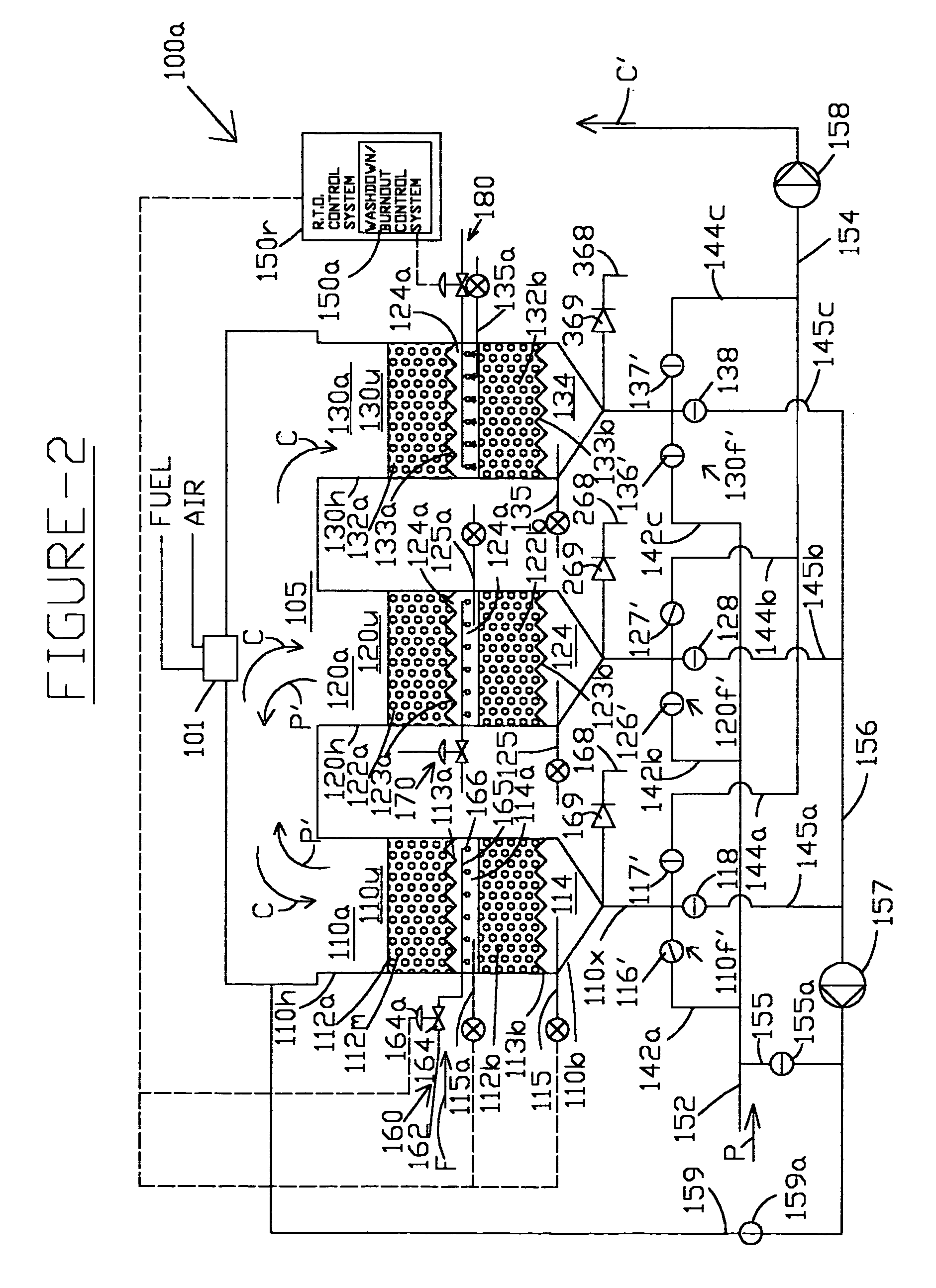
"The present invention relates to a regenerative fume incinerator for cleaning a polluted gas containing organic and inorganic pollutants. The incinerator comprises a combustion chamber and a plurality of regenerative heat exchangers. Each regenerative heat exchanger comprises a regenerative heat sink media bed with a hot end and a cold end. A deposited matter removal means for physically dislodging deposited matter from the surface of the heat sink media bed is located at the cold end. The invention also includes a regenerative heat exchanger control system to perform on-line wash-down of the regenerative heat exchangers and a method of suppressing fires within a regenerative heat exchanger. The technical effects of the invention include improved gas cleaning efficiency, reduced energy consumption, and reduced risk of fire outbreaks."

Problems solved by technology

It is well known in the art that the relatively densely packed heat sink media in the regenerative heat exchangers of regenerative fume incinerators is quite susceptible to fouling due to the deposition of condensable and non condensable aerosols in the polluted air streams.
However, while this “burn-out” (also referred to as “bake-out”) method is useful for removing combustible deposited matter, it is not very useful in removing non-combustible deposited matter from the regenerative heat exchanger.
However, the Noble method suffers from various disadvantages, the primary one of which is that it is mostly manual in nature.
The shut-down and cooling requirement results in an interruption of production for a fairly long period of time.
The Noble method also requires additional time to manually assemble and disassemble the cleaning apparatus in the regenerative fume incinerator.
These time requirements result in lost revenue and profits for the regenerative fume incinerator user.
Further, the Noble method is not effective against sticky combustible deposited matter which cannot be easily dissolved by a water wash.
Cooling the regenerative heat exchanger bed from the higher burn-out temperature requires additional time which further increases loss of production.
This is a particularly difficult fouling situation which requires that the regenerative heat exchanger be first subjected to a burn-out operation to remove the combustible deposited matter and then washed out to remove the residual non-combustible deposited matter such as inorganic salts which are present in wood particles.
The Noble method is not particularly well suited to this application because, during the burn-out operation, the temperature of the heat sink media in the regenerative heat exchanger is raised to a higher level than normal to effect gasification of the combustible matter.
Therefore, the regenerative fume incinerator takes a much longer time to cool to ambient temperature as required in the Noble method.
Further, the Noble method requires operating personnel to open the regenerative fume incinerator and enter into a potentially hazardous confined area, thereby potentially jeopardizing the lives of the personnel.
The Noble method does not disclose a way to selectively clean one or more of the regenerative heat exchangers in a regenerative fume incinerator as needed due to adverse fouling conditions associated with these regenerative heat exchangers.

Method used


Image

  • Regenerative fume-incinerator with on-line burn-out and wash-down system
  • Regenerative fume-incinerator with on-line burn-out and wash-down system
  • Regenerative fume-incinerator with on-line burn-out and wash-down system

Examples


Embodiment Construction

[0022]As defined herein, the term “inlet mode of operation” describes the mode of operation of the regenerative heat exchanger wherein the gas is introduced in to the regenerative heat exchanger from the cold end of the regenerative heat exchanger. The inlet mode of operation occurs when (1) the cold polluted gas is introduced into the regenerative heat exchanger through the inlet damper (a “normal inlet mode of operation”) or (2) a portion of the cooled cleansed gas is recycled back through a purge damper into the cold end of the regenerative heat exchanger to displace the residual polluted gas of the previous cycle into the combustion chamber (a “positive purge mode of operation”).

[0023]Further, as defined herein, the term “outlet mode of operation” describes the mode of operation of the regenerative heat exchanger wherein the gas is introduced into the regenerative heat exchanger from the hot end of the regenerative heat exchanger. The outlet mode of operation occurs when (1) the...


PUM


Abstract

A method and apparatus for on-line wash-down of a heat sink media bed in a regenerative heat exchanger of a regenerative fume incinerator is disclosed. When a heat sink media bed requires cleaning, the selected regenerative heat exchanger is cooled while the remaining regenerative heat exchangers are operated in their normal mode of operation. When the selected media bed reaches a temperature which is less than the thermal-shock temperature of the media material, a cleaning fluid is sprayed on the media surfaces through spray-pipes which are installed within the media bed. After the media surfaces are washed down, the selected regenerative heat-exchanger is reverted back to its normal mode of operation. The regenerative heat exchanger can also be automatically burnt-out of deposited gasifiable matter prior to the wash-down. Random or sequential burn-out and wash-down of the regenerative heat-exchangers can be performed. The apparatus can also be used to suppress fires within the media bed by spraying cold water on the media bed when a rapid rise in temperature is detected within the media bed.

Description

CROSS-REFERENCE TO RELATED APPLICATIONS[0001]This patent application claims priority from U.S. provisional patent application No. 60 / 432,196 filed on Dec. 10, 2002.BACKGROUND OF THE INVENTION[0002]The present invention generally relates to an improved method and apparatus for on-line cleaning of deposited matter from the surfaces of the heat-sink media in Regenerative Fume Incinerators (RFIs). Specifically, it covers a system for washing down the deposited matter from the heat transfer surfaces of the heat sink media (HSM) within a Regenerative Heat Exchanger (RHX) of a regenerative fume incinerator.[0003]Regenerative fume incinerators are widely used in industry to clean polluted gas streams containing combustible pollutants before the gas stream is exhausted to the atmosphere. As used herein, the term “Regenerative Fume Incinerator” includes Regenerative Thermal Oxidizers (RTOs), Regenerative Catalytic Oxidizers (RCO) and Thermal Catalytic Oxidizers (TCO).[0004]Regenerative therma...

Claims


Application Information

Patent Timeline
Patent Type & Authority Patents(United States)
IPC IPC(8): B08B9/00B08B3/00B08B9/093F23G7/06
CPCF23G7/068
Inventor CHILES, JOSEPH DAVIDYERKES, JEFFREY J.KIRKLAND, JOHN G.CABARLO, AGUSTINVIJ, ANU D.
Owner PRO ENVIRONMENTAL
Learn More