Filling station for the filling of fluids

a filling station and liquid technology, applied in liquid handling, container discharging methods, packaging goods types, etc., can solve the problems of unfavorable flow measurement, unfavorable flow measurement, and long filling periods for the system, so as to speed up the filling procedure, reduce maintenance costs, and be more reliable

Inactive Publication Date: 2006-04-04
THERMO KING CORP
View PDF17 Cites 19 Cited by
  • Summary
  • Abstract
  • Description
  • Claims
  • Application Information

AI Technical Summary

Benefits of technology

[0017]The present invention provides a system for the distribution and sale of cryogenic liquid gases, in particular carbon dioxide that is easily accessible for public use by truck drivers and other users that require quick filling of mobile cryogenic tanks or accumulators.
[0018]The system works independently of the level and pressure in the stationary storage tank. The inventive system does not require a transfer pump for transferring the liquid gas from the storage tank to the mobile tank. Therefore, the system is more reliable and maintenance costs are reduced. With the present invention, it is possible to transfer CO2 to the transportable tank while at least some of the CO2 is in a liquid phase, which speeds up the filling procedure.
[0019]Further, the measuring of the transferred liquid under filling is simple and reliable. The filling takes place for instance through a quick connector such as a two-port one-piece connector and no manual valves need to be operated by the operator before or after filling which makes the system easy to use. The filling system is accessible by use of a credit card and the user can thereby be invoiced through ordinary credit card systems.

Problems solved by technology

One disadvantage with the system according to U.S. Pat. No. 5,916,246 for transferring liquid CO2 is that the CO2 loss is relatively high since gaseous carbon dioxide, created as a result of flashing when the pressure of the liquid carbon dioxide is reduced from high pressure in the storage tank to low pressure in the transportable tank, is vented off directly to the atmosphere.
Further, as CO2 is introduced into the transportable tank in both a liquid and a gaseous phase, the system will suffer from unwanted long filling periods and difficulties related to flow measurements.
The known system further requires a skilled person to operate it as the filling operation is not fully automated.
Further, heating a refrigerant to obtain a driving pressure for its transferral is not economic as it reduces the cooling / freezing capacity of the refrigerant.

Method used


Image

  • Filling station for the filling of fluids
  • Filling station for the filling of fluids
  • Filling station for the filling of fluids

Examples


Embodiment Construction

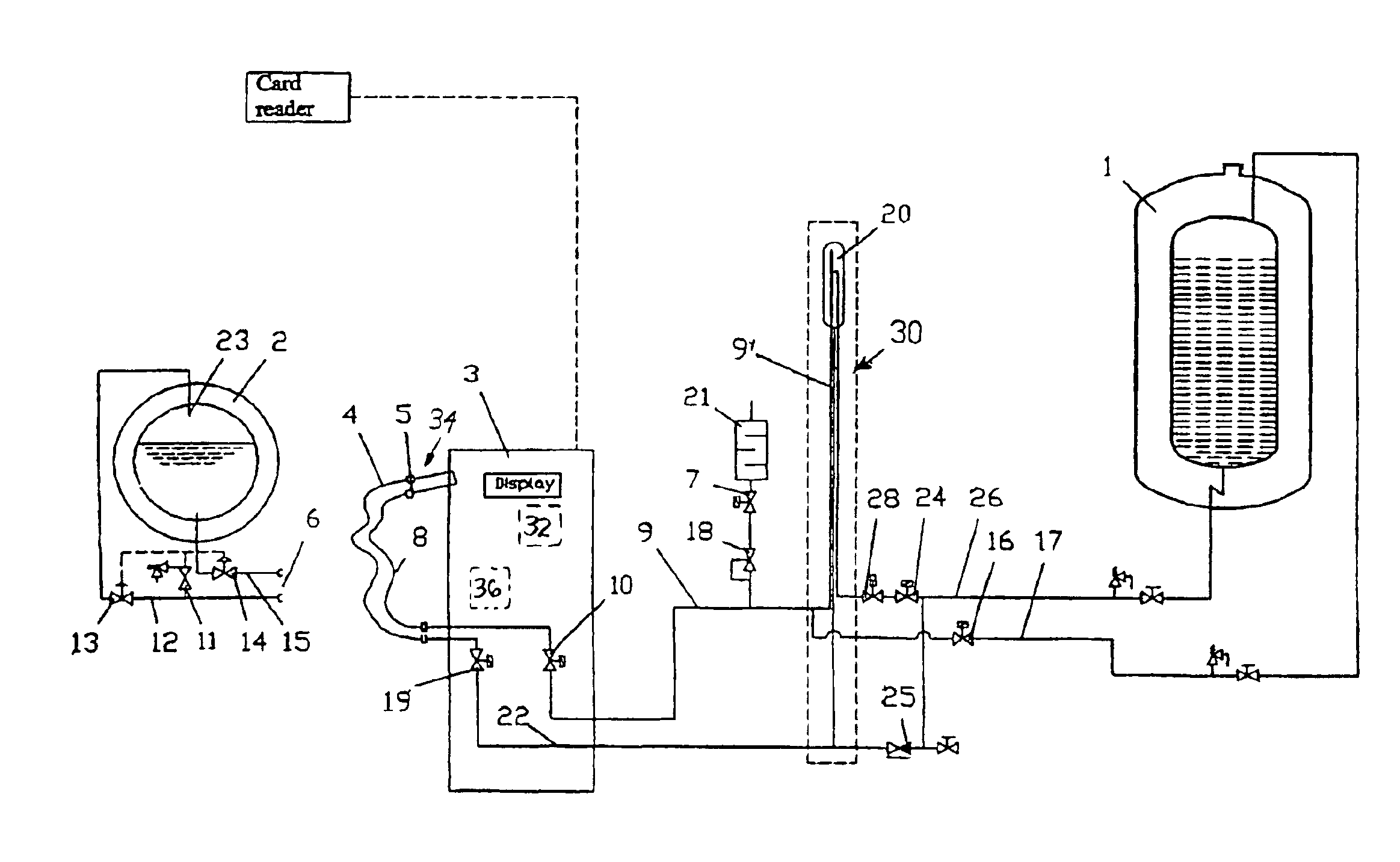
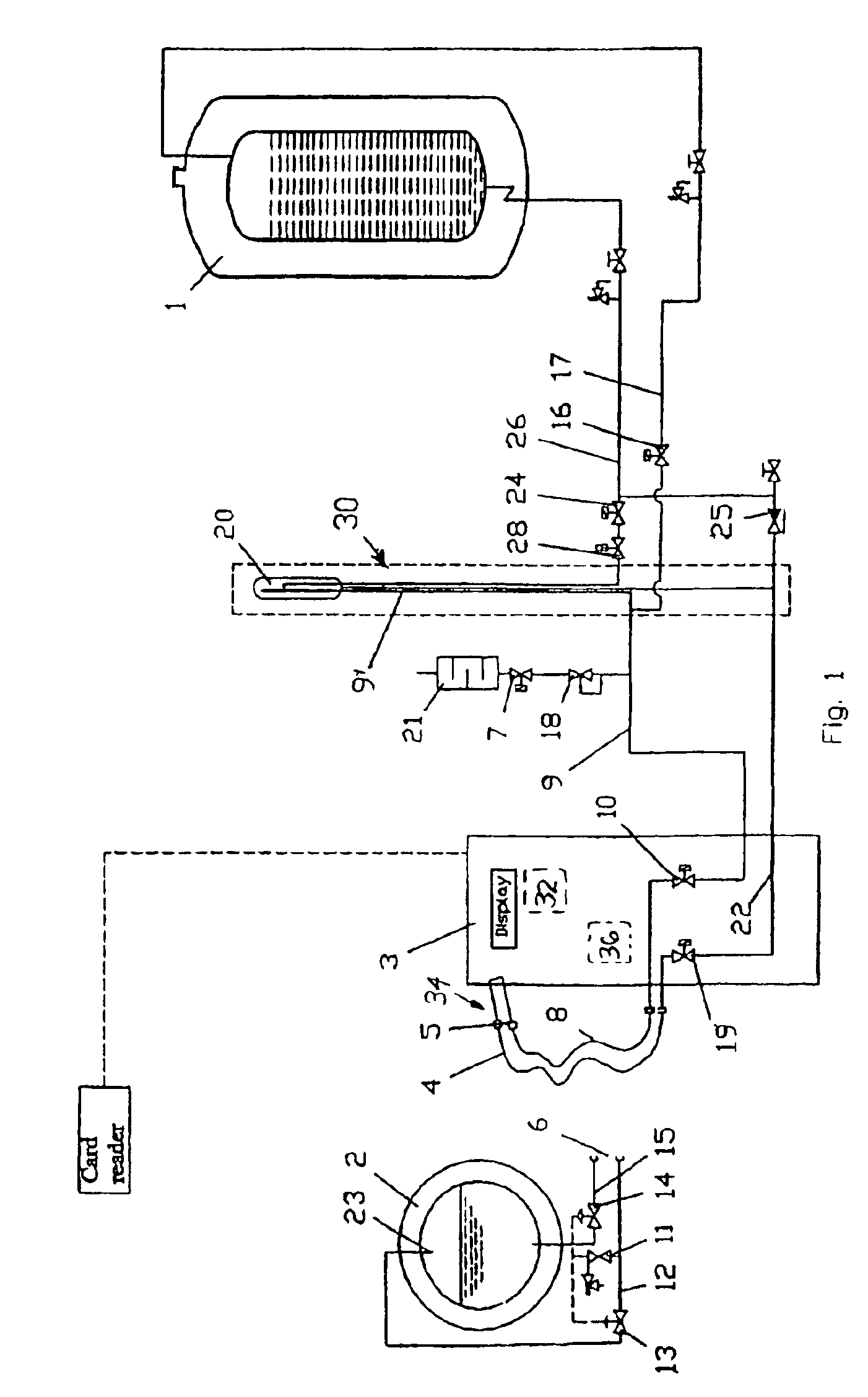
[0025]As shown in the drawings, the filling station of FIG. 1 includes three main components: a stationary storage tank for liquid CO2, 1 a pressure / flow control column 30 (phase separator 20), and a dispenser cabinet 3. These main components are interconnected by means of liquid CO2 piping 26 which extends from the storage tank 1 to the phase separator 20 with a branch pipe 22 extending to the dispenser, and a gas pipe 9 which extends from the dispenser with branch pipes 9′, 17 extending to the phase separator 20 and the tank 1, respectively.

[0026]The stationary storage tank 1 is a standard insulated tank used for different CO2 applications. At different filling stations, the tank size will vary from 12 to 50 m3 depending on the gas turnover at the site. The storage tanks are filled from CO2 trucks operated by a gas supplier.

[0027]Inside the pressure / flow control column 30 the liquid CO2, during mobile tank filling is depressurized, phase separated, and measured. The pressure insid...


PUM

PropertyMeasurementUnit
pressureaaaaaaaaaa
pressureaaaaaaaaaa
gravityaaaaaaaaaa

Abstract

A method for distribution and sales of cryogenic fluids, in particular CO2, includes a system of filling stations for cryogenic fluids provided in connection with ordinary service stations for the filling of fuels to motor driven vehicles. The filling stations for cryogenic fluids include at least a stationary storage tank (1) and dispenser (3) with flexible hoses (4, 8) and a quick connector (5) for easy connection to a mobile tank (2) on a truck or the like. The filling station further includes a pressure/flow control column (27) with a phase separator (20) provided between the stationary storage tank (1) and the dispenser.

Description

[0001]This is a continuation of International Application No. PCT / NO02 / 00493, filed Dec. 20, 2002.FIELD OF THE INVENTION[0002]The present invention relates to a method for the distribution and sale of cryogenic fluids and a filling station for distributing or transferring fluids, in particular cryogenic refrigerants such as CO2, from a storage tank to a mobile tank for instance on a vehicle. The filling station can also include piping, a dispenser with metering equipment for metering the fluid, and a filling hose with a connector for connection to the mobile tank to be filled.BACKGROUND AND SUMMARY[0003]Air conditioning and refrigeration systems of the type used to cool or keep frozen the loads on large trucks and trailers are conventionally based on closed vapor compression cycles.[0004]One alternative to the closed vapor compression cycle is the use of cryogenic refrigeration systems utilizing either liquid carbon dioxide or liquid nitrogen.[0005]In carbon dioxide-based systems, t...

Claims


Application Information

Patent Timeline
Patent Type & Authority Patents(United States)
IPC IPC(8): B65B1/04F17C5/00F17C6/00F17C9/00F17C13/02
CPCF17C5/007F17C6/00F17C9/00F17C13/021F17C2205/0364F17C2205/0367F17C2270/0139F17C2223/0161F17C2250/032F17C2250/036F17C2250/0408F17C2265/065F17C2221/013
Inventor VIEGAS, HERMAN H.ANDERSSON, OSTENHANSEN, TORGEIRSOLVEROD, NILS MAGNUS
Owner THERMO KING CORP
Why Eureka
Try Eureka