Drive train for powering a mobile vehicle

a technology for driving trains and mobile vehicles, applied in positive displacement liquid engines, pump parameters, gearing, etc., can solve problems such as adverse effects on vehicle manufacturing costs, and achieve the effects of high driving resistance, increased delivery volume, and high transmission ratio

Inactive Publication Date: 2006-04-04
ZF FRIEDRICHSHAFEN AG
View PDF12 Cites 9 Cited by
  • Summary
  • Abstract
  • Description
  • Claims
  • Application Information

AI Technical Summary

Benefits of technology

[0007]According to the invention, a smaller drive engine is used, preferably a diesel engine which, with the hydrodynamic converter, is so designed that at the fixed braking point and, when the working hydraulic system is not actuated, the drive engine is running at close to its maximum torque. Since owing to its design, the drive engine will also run at lower speeds in the part-load range, the auxiliary drive and so too the pump of the working hydraulic system will also be driven at lower speeds in the part-load range. To compensate this, either a hydraulic pump with larger delivery volume or a higher transmission ratio between the hydraulic pump and the drive engine is used. This ensures that in the part-load range the working hydraulic system delivers a sufficient quantity. If the drive engine is in full-load operation and its speed is reduced below a defined value because of high driving resistance then, if a large-volume adjustable hydraulic pump is being used for the working hydraulic system, this is adjusted to lower delivery volume or, if a transmission ratio is used between the hydraulic pump of the working hydraulic system and the drive engine, the transmission ratio is increased so that the speed of the hydraulic pump decreases and the take-up performance of the hydraulic pump is reduced, whereby the load on the drive engine will not be unacceptably high. Preferably, the transmission ratio between the hydraulic pump and the drive engine is continuously adjustable, but it is also possible to design the transmission ratio with various shift steps. When an adjustable hydraulic pump is used, the pump is preferably continuously adjustable, but it is also possible to design the hydraulic pump with at least two controllable intake volumes. It is also possible to use several hydraulic pumps, switching off one or more pumps as a function of the speed of the diesel engine so that the volume flow is again reduced.
[0008]This ensures that the hydraulic pump delivers a sufficient quantity for the working hydraulic system in the part-load range without placing too high a load on the drive engine of smaller design.
[0009]In a further embodiment, a clutch can be arranged between the drive engine and the hydrodynamic converter. For example, if the wheel loader is moving at very low speed or even is at rest and the working hydraulic system is actuated, this clutch can be actuated in the opening direction to an extent that a desired driving speed is not exceeded, but a sufficient delivery volume is available for the working hydraulic system since the opening of the clutch increases the speed of the drive engine, but less power flows to the propulsion drive. The clutch can also be used to protect the drive engine from excessive load, since the clutch can always be actuated in the opening direction whenever the propulsion drive and the working hydraulic system cause the drive engine's speed to fall below an acceptable value in order to keep the drive engine running. Preferably, the clutch, between the drive engine and the hydrodynamic converter, and the transmission ratio, between the drive engine and the hydraulic pump of the working hydraulic system, or the delivery volume of the hydraulic pump of the working hydraulic system is controlled or regulated as a function of the desired driving speed, the load condition of the drive engine and the demand of the working hydraulic system.

Problems solved by technology

In most driving conditions, however, the diesel engine is oversized, which has an adverse effect on the manufacturing cost of the vehicle.

Method used


Image

  • Drive train for powering a mobile vehicle
  • Drive train for powering a mobile vehicle

Examples


Embodiment Construction

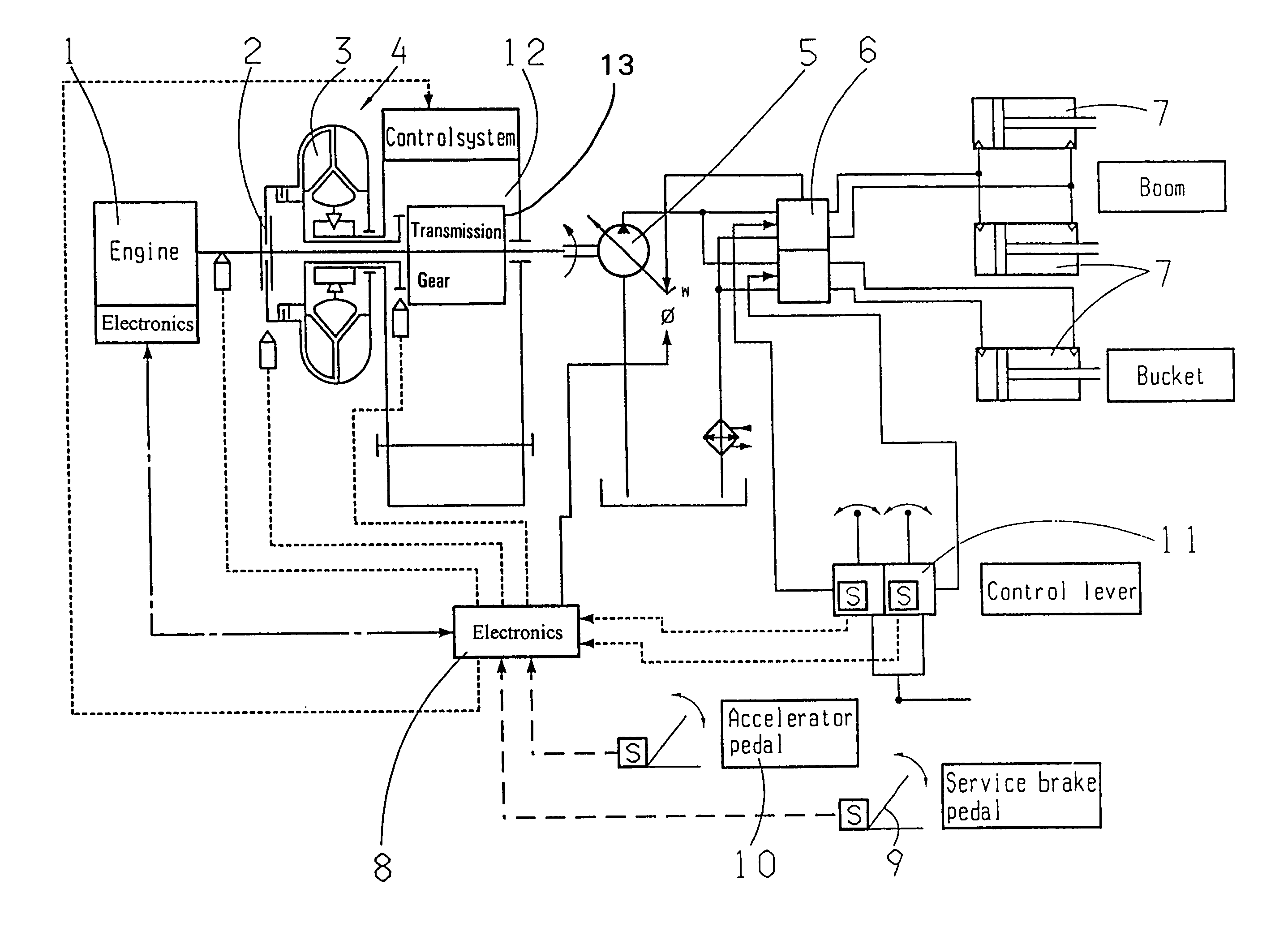
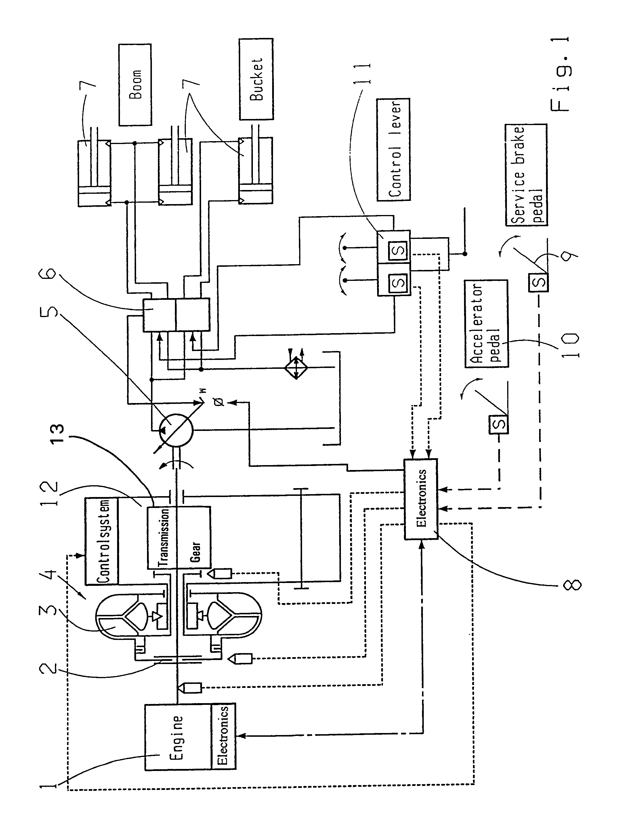
[0012]The single FIGURE shows a drive engine 1, whose output shaft drives a pump impeller 3 of a hydrodynamic converter 4 via a primary clutch 2. The drive engine 1 is also connected to a hydraulic pump 5 of the working hydraulic system. The hydraulic pump 5 can be connected to the drive input of the primary clutch 2. The hydraulic pump 5 is preferably a load-sensing pump. The delivery volume of the hydraulic pump 5 is conveyed to consumer 7 such as the scoop of a wheel loader via a valve 6. An electronic control unit 8 processes signals coming from sensors in a brake pedal 9, a driving speed pedal 10, the control lever 11 for the working hydraulic system, the load condition of the drive engine 1, the speed of the pump impeller 3 and the input speed into the speed-change transmission 12. As a function of these parameters, when the larger hydraulic pump 5 with an adjustable delivery volume is used, the electronic control unit regulates the delivery volume or, when an adjustable trans...


PUM


Abstract

To reduce the structural volume of a drive engine (1) in a drive train of a mobile vehicle, in particular a working machine such as a wheel loader, a continuously adjustable transmission gear is arranged between the drive engine (1) and a hydraulic pump (5) for the working hydraulic system, which can be adjusted as a function of the load condition of the drive engine (1).

Description

[0001]This application claims priority from German Application Serial No. 103 14 329.7 filed Mar. 28, 2003.FIELD OF THE INVENTION[0002]The invention relates to a drive train for powering a mobile vehicle.BACKGROUND OF THE INVENTION[0003]Drive trains of this type are preferably used in working machines such as wheel loaders or graders, in which a drive engine, preferably a diesel engine, is connected to the pump impeller of a hydrodynamic converter whose turbine shaft forms the drive input for a shiftable transmission which is connected to drive wheels. An auxiliary drive for powering at least one hydraulic pump, in particular for the working hydraulic system of the working machine, is also connected to the drive engine and is preferably connected to the drive shaft of the hydrodynamic converter. The drive engine and the hydrodynamic converter are designed so that at the fixed braking point, i.e., when the vehicle is stationary under full load and the working hydraulic system is not ...

Claims


Application Information

Patent Timeline
Patent Type & Authority Patents(United States)
IPC IPC(8): F16H61/40E02F9/22F04B17/00F04B49/20
CPCE02F9/2253E02F9/2296F04B17/00F04B49/20Y10T477/636F04B2201/124F04B2203/0603F04B2203/0604F16H2045/002F04B2201/1201B60W30/00F16H61/40F04C15/00E02F9/22
Inventor LEGNER, JURGENREBHOLZ, WOLFGANG
Owner ZF FRIEDRICHSHAFEN AG
Why Eureka
Try Eureka