
Method for producing porous polyimide resin and porous polymide resin

a technology of porous polyimide resin and porous polyimide, which is applied in the direction of dielectric characteristics, high-frequency circuit adaptations, coatings, etc., can solve the problems of low porosity, inability to achieve sufficient dielectric constant reduction, and easy clogging of pores, so as to prevent flattening or clogging, good high-frequency characteristics, and good mechanical strength

Inactive Publication Date: 2006-04-04
NITTO DENKO CORP
View PDF17 Cites 30 Cited by
  • Summary
  • Abstract
  • Description
  • Claims
  • Application Information

AI Technical Summary

Benefits of technology

[0008]It is the object of the invention to provide a method of producing porous polyimide resin that enables pores to be formed in the precursor of polyimide resin, with the form of the microphase-separated structure wherein a dispersive compound is dispersed in the precursor of polyimide resin being kept unchanged, so as to provide sufficiently reduced dielectric constant and also provide good mechanical strength and heat resistance, and the porous polyimide resin produced by the same producing method.
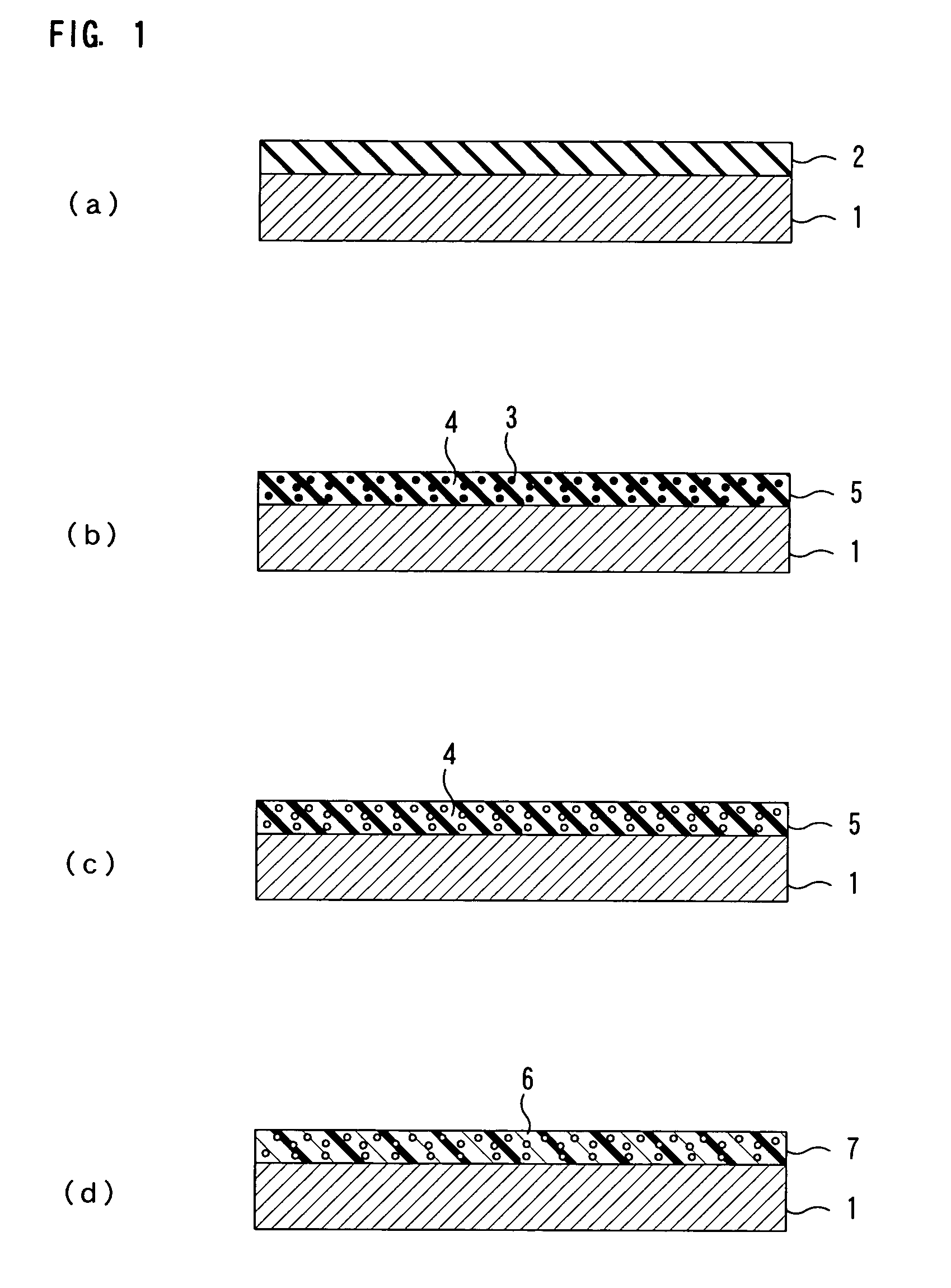
[0013]According to the porous polyimide resin producing method of the present invention, since the form of the pores (cells) in the precursor of polyimide resin obtained by extracting the dispersive compound for removal in the preheating method is retained, the form of the microphase-separated structure can be held as it is in the next imidizing method and accordingly the pores can be effectively prevented from being flattened or clogged. Due to this, even the similarly sized microscopic pores (cells) having an average pore size of e.g. 1 μm or less can be well formed without being clogged or closed and, as a result of this, the porous polyimide resin having a dielectric constant as low as not more than 3 or further not more than 2.5 can be obtained.
[0014]Accordingly, since the porous polyimide resin of the present invention can provide good high-frequency characteristics, mechanical strength, and heat resistance, the porous polyimide resin of the present invention can be effectively used as polyimide resins used in the electronic / electric equipment and the electronic components for storing large amounts of information, processing them rapidly, and transmitting them at high speed, including internal insulating material of the electronic equipment, cushioning material and an insulating layer of the circuit board.

Problems solved by technology

However, when the pores are formed in the precursor of polyimide resin by removing hydrophilic polymer by baking it or by extraction of the solvent, followed by imidization of the precursor of polyimide resin, the pores are flattened or clogged, so that the porosity is reduced below the ideal one, resulting in a problem that sufficient reduction of the dielectric constant cannot be obtained.
Although it is preferable that the pores has a smaller diameter to retain mechanical strength and heat resistance of the porous polyimide resin produced, when the pores are reduced to a diameter as small as 1 μm or less, there arises the specific problem that the pores may be clogged with ease.

Method used


Image

  • Method for producing porous polyimide resin and porous polymide resin
  • Method for producing porous polyimide resin and porous polymide resin
  • Method for producing porous polyimide resin and porous polymide resin

Examples


example 1

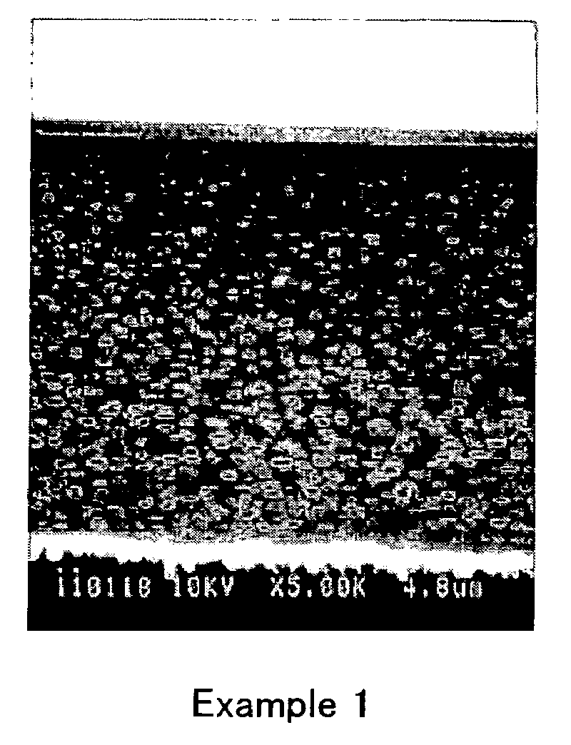
[0063]30 parts by weight of the solution of the precursor of polyimide resin obtained in the synthesizing example 2 was mixed with 70 parts by weight of the solution of the precursor of polyimide resin obtained in the synthesizing example 1, to obtain the mixed solution of the precursor of polyimide resin. Then, polyethylene glycol dimethylether having the weight-average molecular weight of 500 was blended in the mixed solution of the precursor of polyimide resin in the proportion of 66 parts by weight per 100 parts by weight of resin contents in the mixed solution of the precursor of polyimide resin and was stirred, to obtain transparent homogeneous resin solution.

[0064]Then, the resin solution thus obtained was applied to a stainless foil (SUS304) having thickness of 25 μm by using the spin coater so that the coating could have thickness of 21 μm after dried. Then, the resin solution was dried at 95° C. for ten minutes in a hot-air circulation oven to release NMP therefrom. Therea...

example 2

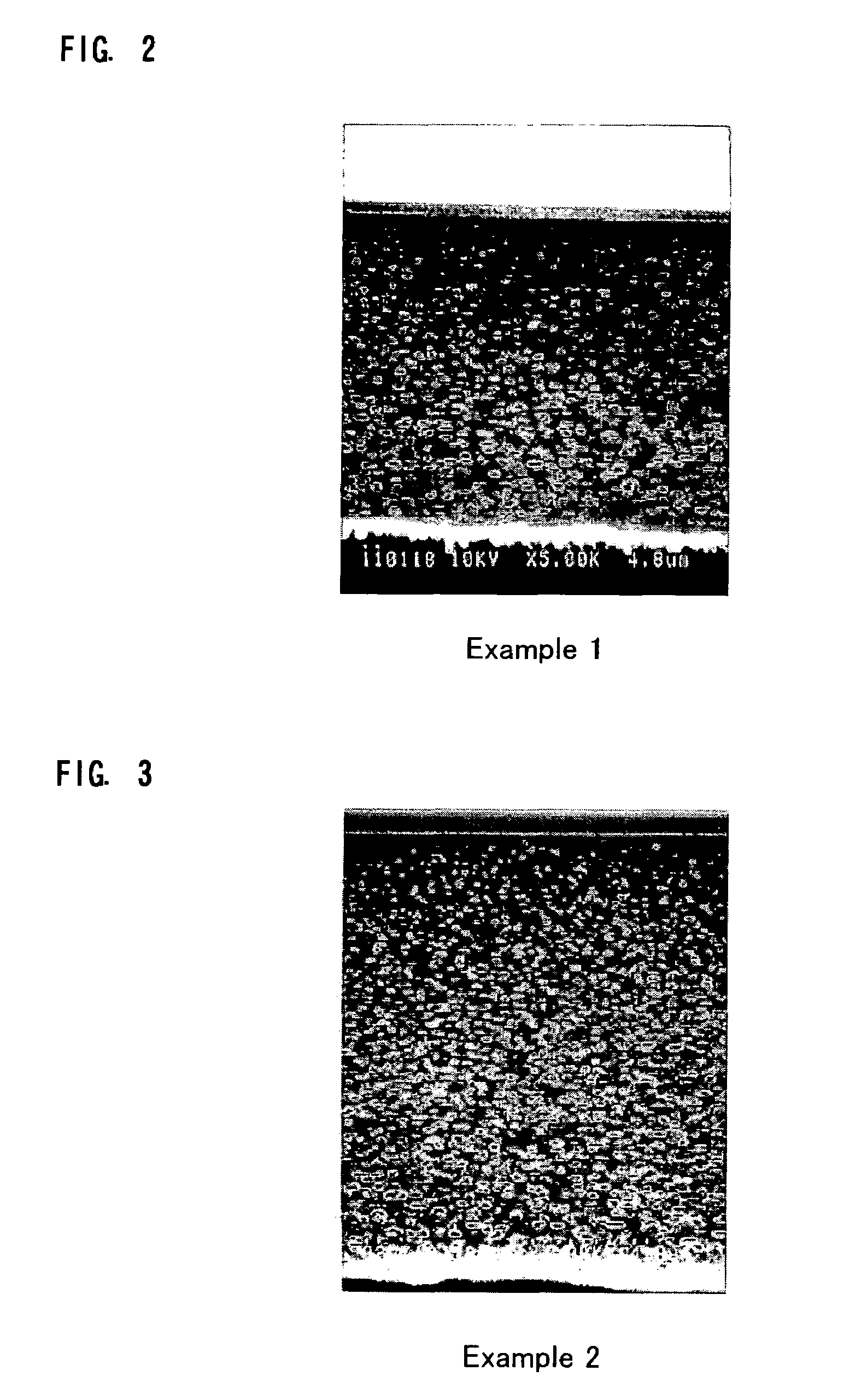
[0071]Except that polyethylene glycol dimethylether having the weight-average molecular weight of 500 was blended in the mixed solution of the precursor of polyimide resin in the proportion of 80 parts by weight per 100 parts by weight of resin contents in the mixed solution of the precursor of polyimide resin, to prepare the resin solution, the same operations as the operations of Example 1 were made to form the coating comprising the porous polyimide resin.

[0072]The SEM observation image of a sectional view of the coating comprising the porous polyimide resin obtained was made by the image processing. The result is shown in FIG. 3. The size of the pores (cells) calculated by the image processing was 0.194 μm. Also, the dielectric constant (ε) of the coating obtained was 2.200 (measuring frequency: 1 MHz).


PUM

PropertyMeasurementUnit
Temperatureaaaaaaaaaa
Particle sizeaaaaaaaaaa

Abstract

A method of producing porous polyimide resin that enables pores to be formed in a precursor of polyimide resin, with its form of microphase-separated structure wherein a dispersive compound is dispersed in the precursor of polyimide resin being kept unchanged, so as to provide significantly reduced dielectric constant and also provide improvement in mechanical strength and heat resistance, and the porous polyimide resin produced in the same producing method. A coating comprising porous polyimide resin is formed by applying resin solution comprising a precursor of polyimide resin and a dispersive compound and then drying a solvent, to form a coating in which the dispersive compound is dispersed in the precursor of polyimide resin; extracting the dispersive compound from the coating for removal to make the precursor of the polyimide resin porous; and imidizing the coating after preheated in a temperature range of 190–250° C.

Description

[0001]This application is a 35 U.S.C. 371 National Stage entry of PCT / JP02 / 06991, filed Jul. 10, 2002, which claims priority from Japanese Patent Application No. 2001-213274, filed Jul. 13, 2001, the contents of which are herein incorporated by reference to the extent allowed by law.TECHNICAL FIELD[0002]The present invention relates to a method of producing porous polyimide resin and to porous polyimide resin. More particularly, the present invention relates to a method of producing porous polyimide resin suitably used as insulating material for electronic / electric equipment and electronic components and to porous polyimide resin produced by the same producing method.BACKGROUND ART[0003]In general, polyimide resin has a high insulation performance. Accordingly, the polyimide resin is widely applied to electronic / electric equipment and electronic components including circuit boards and printed wiring boards as parts or components requiring high reliability.[0004]In recent years, elec...

Claims


Application Information

Patent Timeline
IPC IPC(8): B05D3/02B05D3/10C08J9/36C08J9/26H05K1/02H05K1/03
CPCC08J9/26H05K1/0346C08J2201/0502C08J2379/08H05K1/024H05K2203/0773H05K2201/0154H05K2201/0355H05K2203/0156H05K2203/0759H05K2201/0116C08J9/24
Inventor KANADA, MITSUHIROFUKUOKA, TAKAHIROKINJOU, NAOTAKA
Owner NITTO DENKO CORP
Learn More