Moving crank mechanism

a crank mechanism and crank technology, applied in the field of conveyor mechanisms, can solve the problems of low cost and uncomplicated storage systems that are not very efficient or flexible in their ability, complex and expensive systems, and the ability of low cost and uncomplicated storage systems to achieve the effects of fast access, fast access, and increased efficiency and flexibility of the system

Inactive Publication Date: 2006-04-11
LICHTI ROBERT D +1
View PDF5 Cites 77 Cited by
  • Summary
  • Abstract
  • Description
  • Claims
  • Application Information

AI Technical Summary

Benefits of technology

[0020]Vertical lifts according to the present invention, when used in a two way high speed storage system substantially increase the efficiency and flexibility of the system in handling objects such as containers. Back-up on the conveyor track when the storage carousel is near full capacity is eliminated because the objects can remain indefinitely on the vertical until on open location on the storage carousel arrives. In addition, possible collisions between objects on the reciprocating shuttle and on the storage carousel are eliminated. Objects can more quickly be handled in transport between the storage carousel and the conveyor tracks because the vertical lift can be driven in multiple increments of the distance between two adjacent shelves, as desired. In addition, objects are not committed for transport to the storage carousel or to a specific spot on the storage carousel when they are placed on the vertical lift. If desired, an object can be transferred back to the conveyor assembly without having to be inserted onto and extracted from the storage carousel.
[0021]A particularly preferred embodiment of the present invention contemplates the use of the vertical lift as the primary storage location in an automated storage system. Typically, several vertical lifts are placed in operative association with a conveyor system. The vertical lifts can be distributed throughout the system as needed, unlike a rotary carousel based system. In general, the vertical lift based storage systems will have from approximately 10 to 30 shelves on each reach. Thus, when an object is to be retrieved from a vertical lift that can be driven in both directions, it is at the most no more than approximately 10 to 30 shelve widths away from the insertion and extraction level. In a vertical lift that can only be driven in one direction, an object is no more than approximately 20 to 60 shelf widths away from the insertion and extraction level. This provides very fast access to the desired objects during both the extraction and insertion phases of the operation. Very fast access can be achieved even while the vertical lift is operating at low speeds. Since insertion and extraction always occur at the same level, preferably when the lift is stationary, no mechanism is required to move objects between a conveyor level and a storage level, or to synchronize the movement of the inserters and extractors with the movement of the lift. Insertion and extraction can be automated with simple pusher mechanisms, or they can be performed manually. The vertical lifts can operated continuously, if desired. Continuous operation may be desirable, for example, when the load on the lift is so heavy that stopping and starting the vertical lift would impose unacceptable loads on the mechanism. The location of objects on the vertical lifts in a system can be accounted for and tracked by appropriate software, and identification devices, as will be understood by those skilled in the art. Automation of a vertical lift based storage system is easier and simpler than is the automation of a rotary storage carousel system, because, inter alia, the timing of the handling of the objects is simpler, and less handling is involved in the insertion and extraction operations.

Problems solved by technology

Previous expedients in developing high speed storage systems having increased efficiency and flexibility in transporting containers or other objects between a conveyor system and a storage carousel system have resulted in complex and expensive systems.
Typically, low cost and uncomplicated storage systems are not very efficient or flexible in their ability to handle objects of various sizes in a variety of situations.
In general, one of the constraints in prior art rotary carousel systems had been the fact that most vertical lifts could not carry objects over the top or around the bottom of the lift.

Method used


Image

  • Moving crank mechanism
  • Moving crank mechanism
  • Moving crank mechanism

Examples


Embodiment Construction

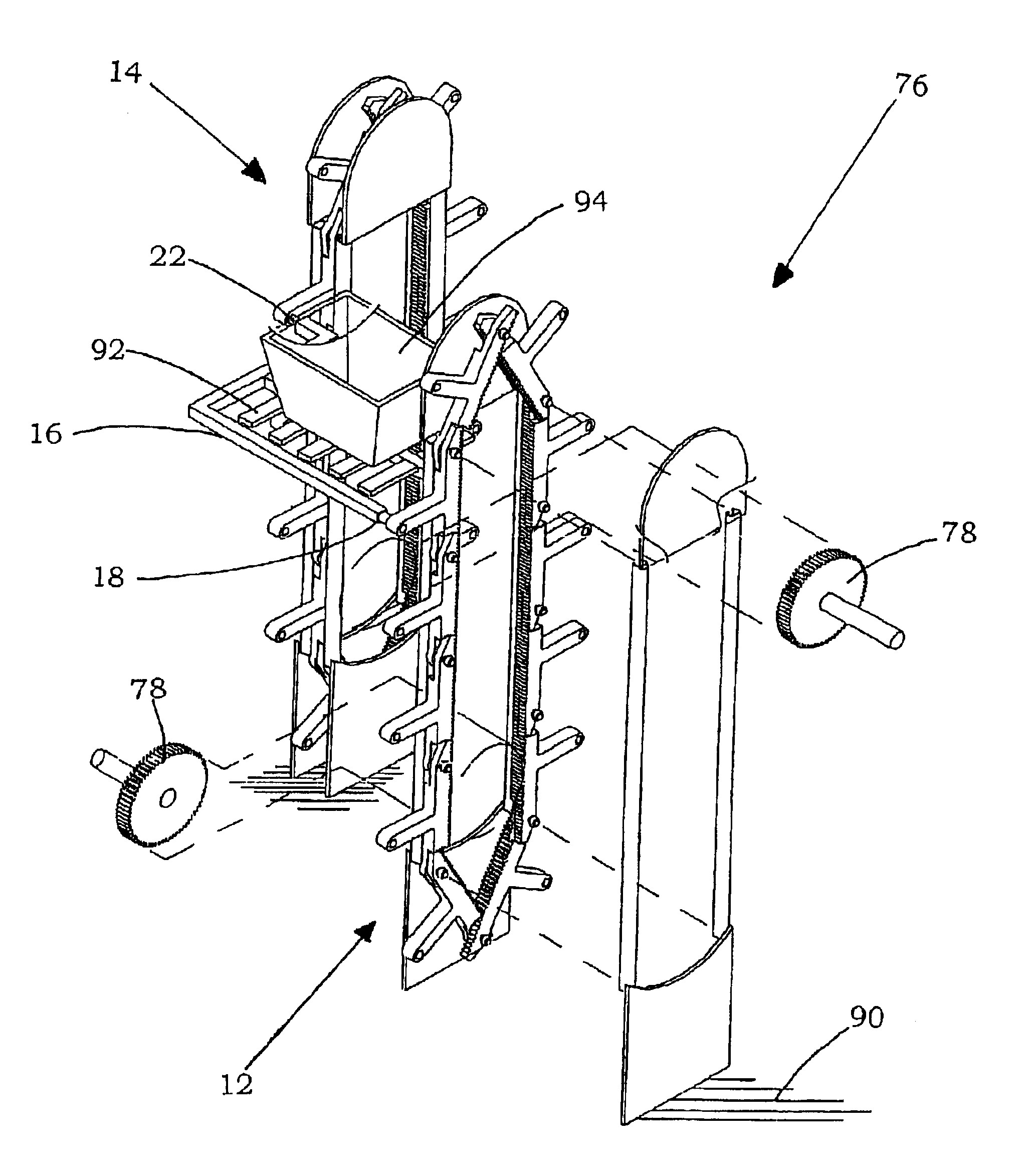
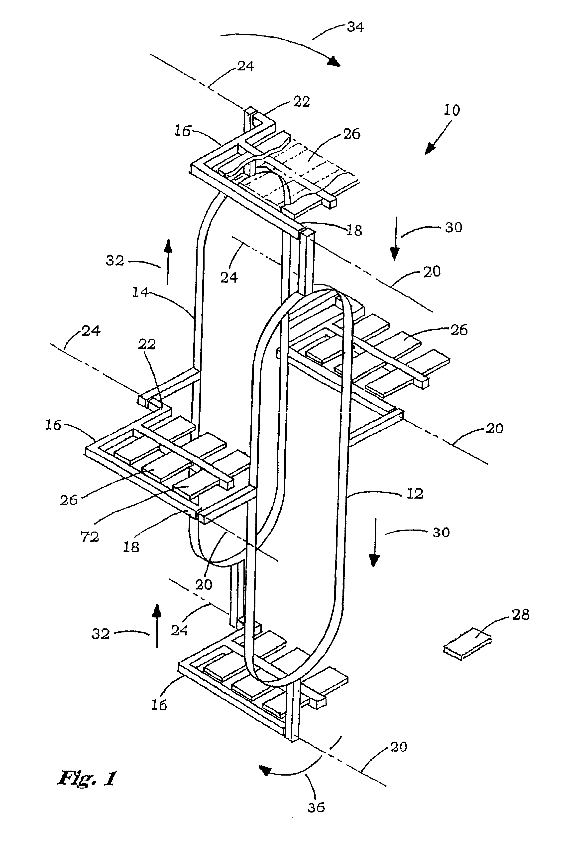
[0038]Referring now to the drawings, for the purposes of illustration and not limitation, wherein like reference numerals designate identical or corresponding parts throughout the several views, there is illustrated generally at 10 a vertical lift mechanism of the present invention wherein the endless loops 12 and 14 are offset horizontally from one another.

[0039]The moving crank mechanism is shown schematically in FIG. 1 to facilitate the discussion of the unique features of the mechanism and its operation. The moving crank mechanism 10 comprises a first endless loop 12, a second endless loop 14, and a plurality of crank members 16. Each crank member has a first journal end 18 establishing a first axis 20 and an opposed second journal end 22 establishing a second axis 24. It is significant that the opposed first and second axes for each crank member are offset and substantially parallel to one another. This parallel offset establishes a crank plane between the axes for each crank m...


PUM


Abstract

A moving crank mechanism that is particularly adapted for use in a conveyor system. A moving crank remains in a substantially parallel position with respect to a fixed reference plane as the crank member is driven by its offset opposed ends along an endless loop. The closed loop vertical lift unit is adapted for use in an automated high-speed storage system. The vertical lift unit is adapted to be used as a primary storage location or as a lift for carrying objects in transit between levels in a storage system. The vertical lift unit includes a plurality of crank members with generally rigidly mounted shelves that are adapted to carry objects continuously and indefinitely as the shelves travel through a vertically oriented closed path. While traveling along the vertically oriented closed path the shelves remain parallel to a fixed horizontal plane so objects can be carried on the shelves while the shelves transition between the up and down reaches of the vertical lift mechanism. The opposed ends of the crank member are journaled in carriage members that are mounted to carry the respective ends of the crank member around the closed loop. The respective ends are carried around the closed loop at about the same rate. The closed loops are offset from one another by the amount of the crank offset. Shelf stabilizing mechanisms can also be employed.

Description

RELATED APPLICATIONS[0001]Claims priority of United States of America Provisional Application Ser. No. 60 / 196,245, filed Apr. 09, 2000, and PCT / US01 / 11485, filed Apr. 09, 2001.BACKGROUND OF THE INVENTION[0002]1. Field of the Invention[0003]The invention relates in general to a conveyor mechanism wherein the conveying elements remain substantially parallel to a fixed reference plane as the conveying elements continuously travel around a closed endless loop or path, and, in particular, to a closed loop vertical lift mechanism adapted for use in an automated storage system.[0004]2. Description of the Prior Art[0005]Previous expedients in developing high speed storage systems having increased efficiency and flexibility in transporting containers or other objects between a conveyor system and a storage carousel system have resulted in complex and expensive systems. Typically, low cost and uncomplicated storage systems are not very efficient or flexible in their ability to handle objects ...

Claims


Application Information

Patent Timeline
Patent Type & Authority Patents(United States)
IPC IPC(8): B65G1/00B65G17/16B65G37/00B65G1/12B65G1/127B65G1/133B65G17/12B65G47/57
CPCB65G1/127B65G1/133B65G47/57B65G17/123B65G2201/02
Inventor LICHTI, ROBERT D.LICHTI, WAYNE
Owner LICHTI ROBERT D
Why Eureka
Try Eureka