Expansion matched thin disk laser and method for cooling

Inactive Publication Date: 2006-04-11
NEWPORT CORP
View PDF11 Cites 34 Cited by
  • Summary
  • Abstract
  • Description
  • Claims
  • Application Information

AI Technical Summary

Benefits of technology

[0014]These and other objects of the present invention are provided in an optical system that includes a diode pump source and a thin disk gain media. The thin disk gain media has first and second surfaces and is made of a material with an anisotropic thermal expansion. At least one of the first and second surfaces is a cooling surface. The thin disk gain media is cut at an angle to provide substantially the same thermal expansion coefficient in all directions lying in a plane that is parallel to the cooling surface. An optical coupler is positioned between the diode pump source and the thin disk gain media to direct an output from the diode pump source to the thin disk gain media.
[0015]In another embodiment of the present invention, a method of producing an output beam from

Problems solved by technology

Different thermal expansion coefficients impose a severe problem for bonded structures as the mechanical stress that is induced through unequal expansion/contraction during thermal changes can break the bond.
For thin materials non-uniform expansion can also induce fracture during coating processes that tend to heat the substrate.
Thermal fracture imposes a particular problem for double-tungstate laser materials such as Yb:KYW, Yb:KGW, KYbW, Nd:KGW, Nd:KYW, when these materials are to be used in a thin disk geometry.
The drawback of using such a thick indium layer is that the thermal conductivity is low, such that the temperature of the

Method used


Image

  • Expansion matched thin disk laser and method for cooling
  • Expansion matched thin disk laser and method for cooling
  • Expansion matched thin disk laser and method for cooling

Examples


Embodiment Construction

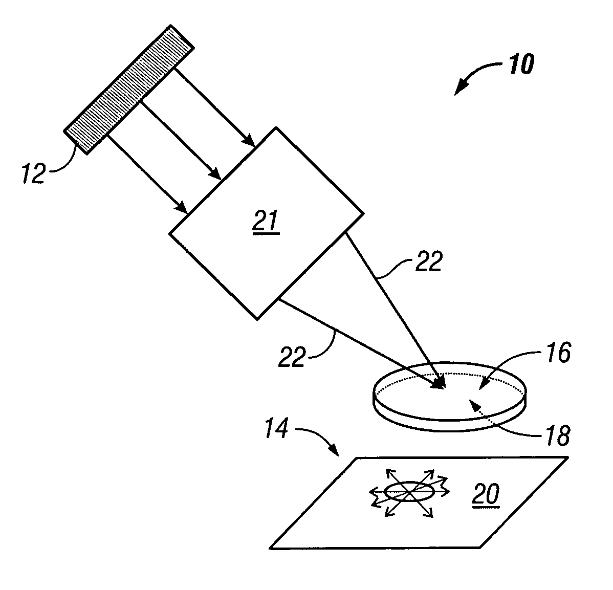
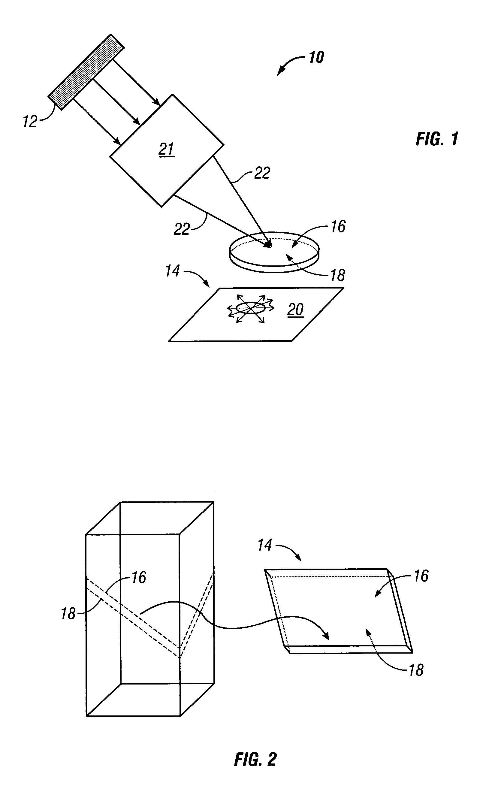
[0022]In one embodiment of the present invention, illustrated in FIGS. 1 and 2, an optical system 10 includes a diode pump source 12. Suitable diode pump sources 12 include but are not limited to a fiber-coupled diode, a diode bar, a stack of diode bars, and the like. Laser system 10 can be a laser system, a multi-pass amplifier system, a regenerative amplifier system and the like.

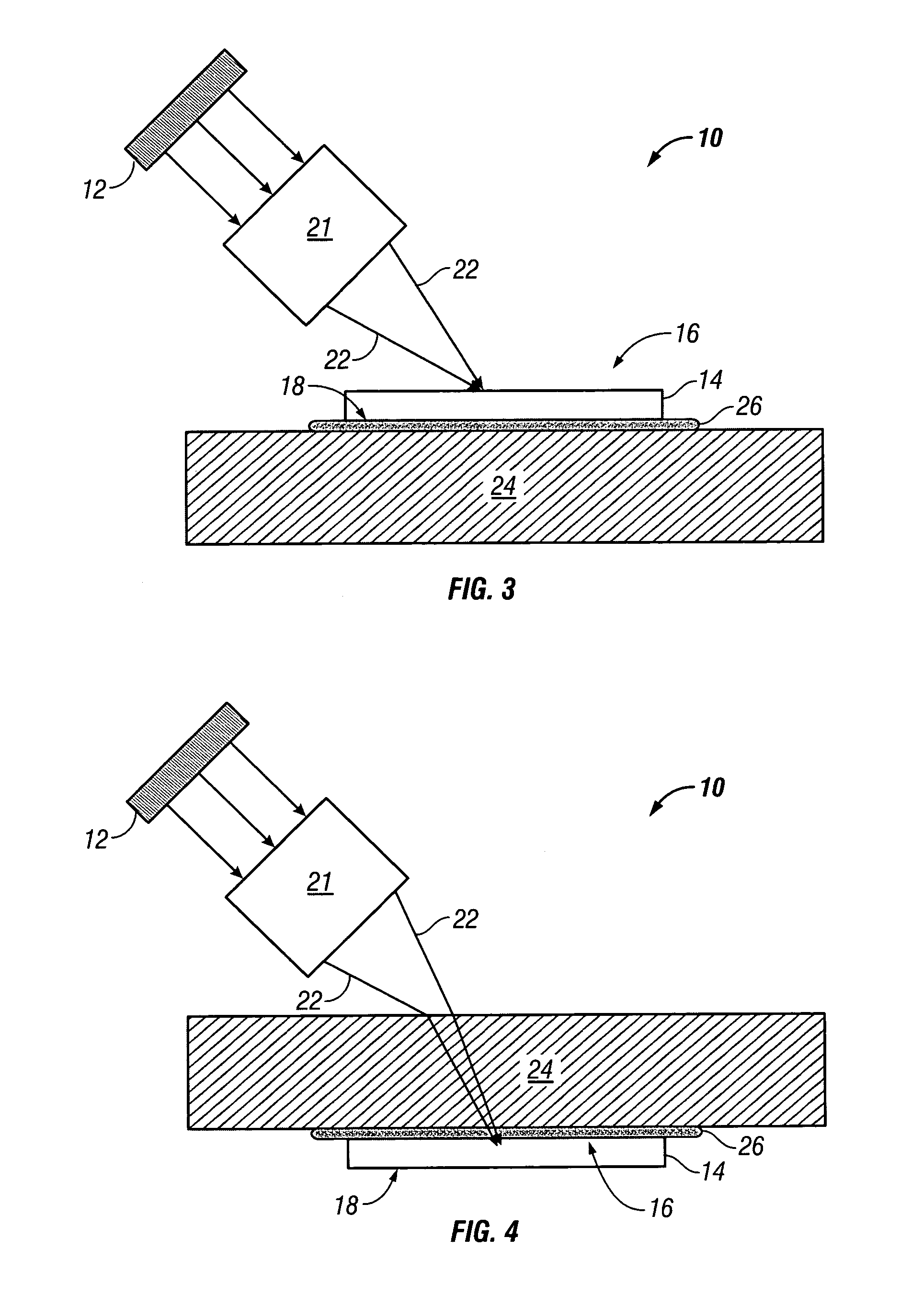
[0023]A thin disk gain media 14 has two surfaces 16 and 18. Thin disk gain media 14 can be made of a gain material that has an anisotropic thermal expansion. Thin disk gain media 14 is cut at an angle to provide substantially the same thermal expansion coefficient in all directions lying in a plane 20 that is parallel to surfaces 16 and 18. In one embodiment, surface 16 is an incidence surface, and surface 18 is a cooling surface. In another embodiment, surface 16 is both an incidence and a cooling surface.

[0024]An optical coupler 21 is positioned between diode pump source 12 and thin disk gain media 14 to...


PUM


Abstract

An optical system includes a diode pump source and a thin disk gain media. The thin disk gain media has first and second surfaces and is made of a material with an anisotropic thermal expansion. At least one of the first and second surfaces is a cooling surface. The thin disk gain media is cut at an angle to provide substantially the same thermal expansion coefficient in all directions lying in a plane that is parallel to the cooling surface. An optical coupler is positioned between the diode pump source and the thin disk gain media to direct an output from the diode pump source to the thin disk gain media.

Description

BACKGROUND OF THE INVENTION[0001]1. Field of the Invention[0002]This invention relates to a thin disk gain medium for a laser and more particularly to a thin disk gain medium with an anisotropic thermal expansion.[0003]2. Description of Related Art[0004]Different thermal expansion coefficients impose a severe problem for bonded structures as the mechanical stress that is induced through unequal expansion / contraction during thermal changes can break the bond. For thin materials non-uniform expansion can also induce fracture during coating processes that tend to heat the substrate. In this context “bonding” therefore includes coating the first material with a second material or multiple layers, e.g. depositing a dielectric coating on a thin laser crystal. It also includes soldering a thin laser crystal to a heat sink using a third material like indium during which process the structure is heated above the melting point of said third material and cooled to form a solid bond. Thermal fr...

Claims


Application Information

Patent Timeline
IPC IPC(8): H01S3/091H01S3/04H01S3/042H01S3/06H01S3/08H01S3/092H01S3/0941H01S3/16
CPCH01S3/042H01S3/0627H01S3/09415H01S3/0405H01S3/0604H01S3/1618H01S3/08072H01S3/0606
Inventor SUTTER, DIRKKAFKA, JAMES D.
Owner NEWPORT CORP
Why Eureka
Try Eureka