Construction layout stripping having a plurality of pairs of uprights thereon

a construction layout and upright technology, applied in the direction of building roofs, ceilings, building repairs, etc., can solve the problems of time-consuming and error-prone use of tape measurers and markers, and the device of hascall is not designed to work with wooden studs, so as to reduce the actual installation time of all framing members.

Inactive Publication Date: 2006-04-18
WINCHESTER RICHARD M
View PDF34 Cites 16 Cited by
  • Summary
  • Abstract
  • Description
  • Claims
  • Application Information

AI Technical Summary

Benefits of technology

[0013]It is an object of the present invention to provide a method for assembling construction elements comprising the steps of providing construction layout stripping according to the present invention, placing a plurality of framing members into the partitions adapted to receive them at the desired fixed intervals, in preparation for the fixing of members in place at the desired interval. The layout of construction projects, commercial and residential, in the past took considerable time by the project's lead carpenter, and most times an additional assistant. Construction layout stripping requires only one person who does not have to be a lead carpenter or even be trained in carpentry layout procedures. With construction layout stripping, one man can perform the same task—mistake proof—in one-half the time. The actual installation time required of all framing members is also greatly reduced due to the fact the construction layout stripping's uprights hold all members in place while nailing.
[0014]It is also an object of the invention to eliminate the need for measurement and marking of locations for construction members. Construction layout stripping allows work in all kinds of weather under which construction typically takes place. Whereas previously rain, ice or other inclement weather could obscure pencil marks, construction layout stripping is not affected by the weather due to the fact that construction layout stripping will be manufactured out of water resistant materials. Adverse factors common to construction sites such as cold, heat, rain, snow, ice, dirt, sawdust, etc., will not result in construction delays as in the past with lead pencil layout markings.
[0015]Finally, it is an object of the present invention to provide construction layout stripping which can be used in the manufacturing industry. For example, where manufactured items require spacing similar elements at regular fixed intervals, construction layout stripping could easily be adapted to the needs of a manufacturing process.

Problems solved by technology

Use of a tape measurer and a marker is time consuming and subject to mistakes.
Great difficulty is encountered by the installer attempting to hold multiple construction members in place in preparation for permanently affixing them in position.
However, Hascall's device was not designed to work with wooden studs.
In addition, it is relatively expensive.
Thus, Hascall's device is only useful for metal studs for framing wall members.
Other construction elements such as roofs, sub-floors, trusses, and other such elements could not be used with this particular device.

Method used


Image

  • Construction layout stripping having a plurality of pairs of uprights thereon
  • Construction layout stripping having a plurality of pairs of uprights thereon
  • Construction layout stripping having a plurality of pairs of uprights thereon

Examples


Embodiment Construction

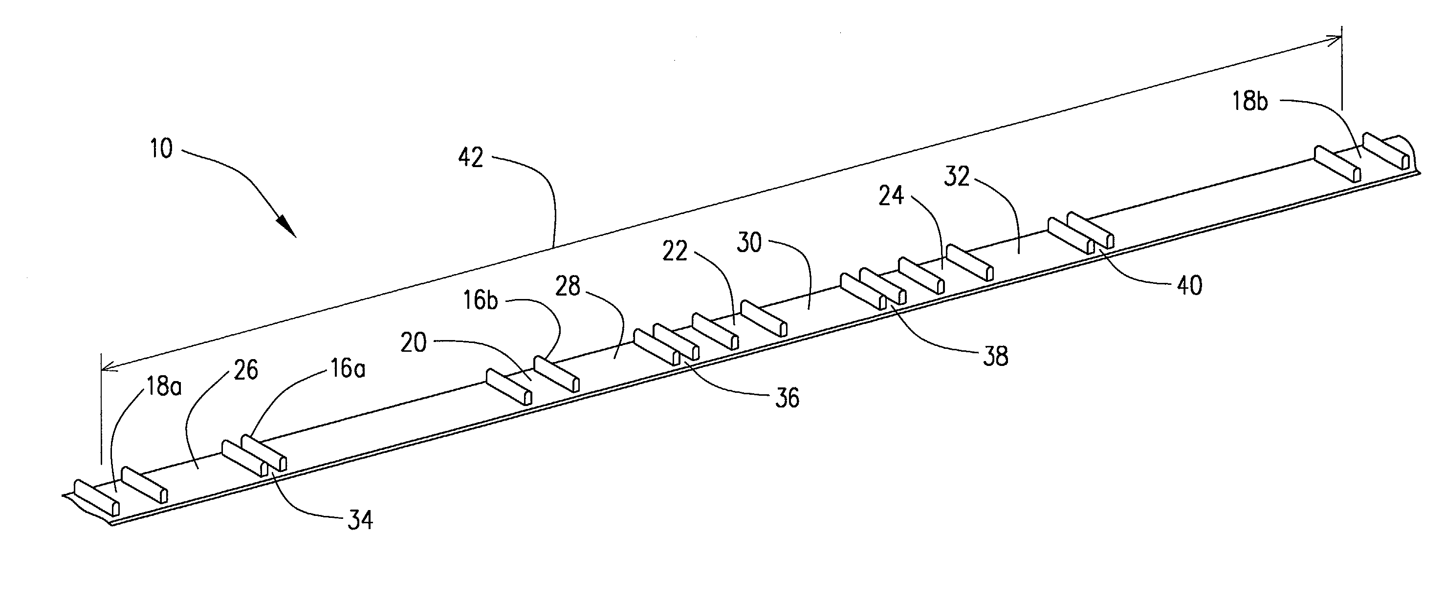
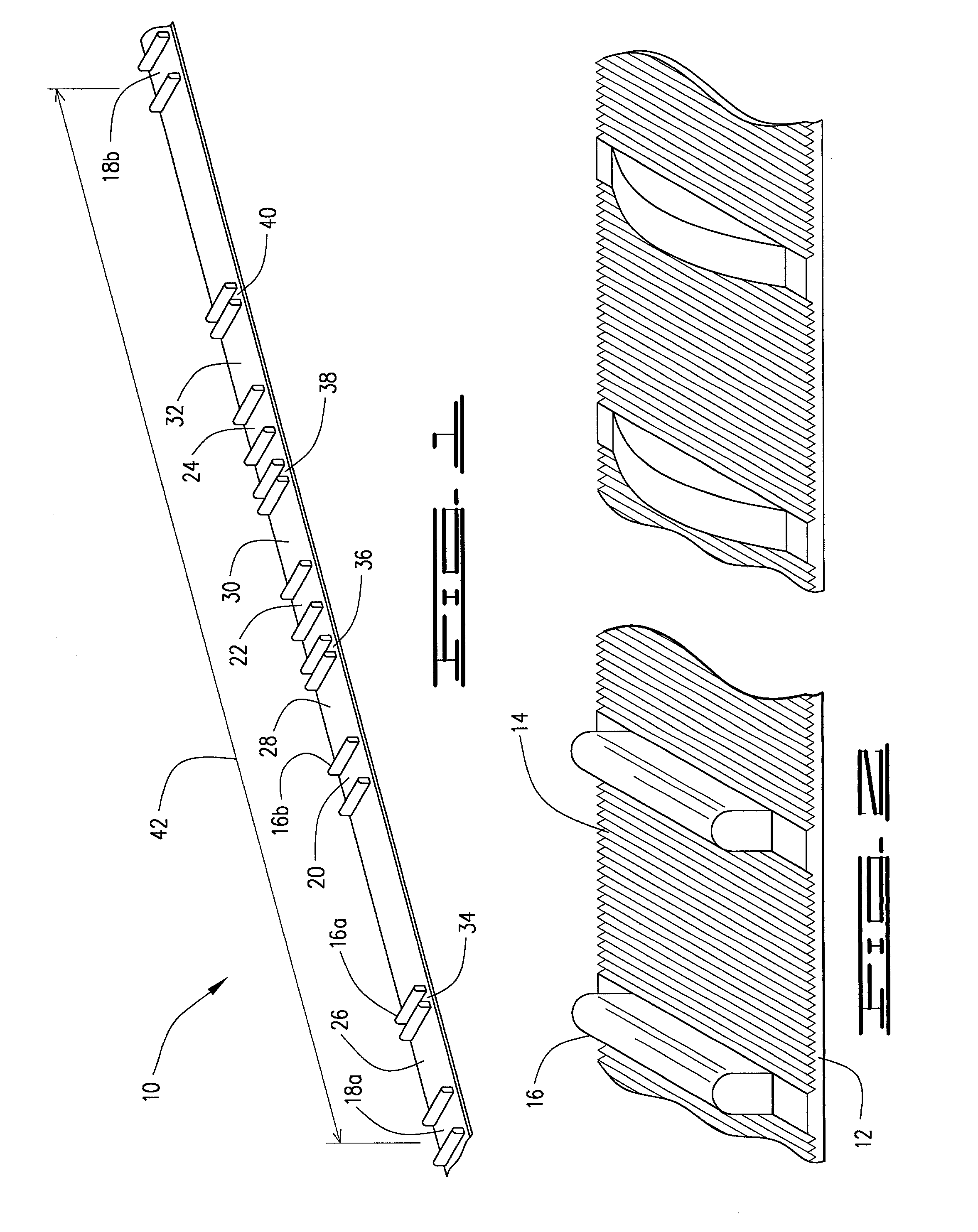
[0032]Referring now to the drawings, where like numerals represent like parts, the construction layout stripping 10 is generally shown in FIG. 1. It has a base 12 which is comprised of a pliable, non-elastic elongated material. The material will be as non-elastic as possible so stretching or contracting of the fixed spacing on the partitions will be insignificant. The base 12 may be constructed from fabrics of various sorts, such as cotton, nylon, rayon, silk, and the like. However, the base 12 will preferably be composed of rubber, plastic, polyvinyl chloride, polyethylene, high density polyethylene, rayon, natural rubber, or other similar materials. Where rubber or plastic materials are used, it must be kept in mind that the strip must be non-elastic. Whatever materials are chosen, they must have a relatively low coefficient of thermal expansion / contraction. That is, a material which expands or contracts significantly in response to changes in temperature is not a suitable materia...


PUM


Abstract

A construction layout stripping and method for laying out construction members or framing members at a fixed distance interval from one another. The construction layout stripping comprises: first, a pliably, non-elastic elongated base; and second, repeating units disposed on the base, the repeating units having a plurality of pairs of uprights at fixed intervals, each pair of uprights defining a partition for receiving a specified size of framing member. In a preferred embodiment, the construction layout stripping has upright defining spaces for receiving 1⅝″, 3⅝″, and ½″ framing members on either 16″ or 24″ centers using the same construction layout stripping. The construction layout stripping may have cutting ribs defined thereon for cutting the stripping at a desired length.

Description

CROSS REFERENCES TO RELATED APPLICATIONS[0001]This application is a continuation-in-part of U.S. patent application Ser. No. 09 / 356,300 for Construction Layout Stripping, filed Jul. 16, 1999 now abandoned.BACKGROUND OF THE INVENTION[0002]a. Field of the Invention[0003]The invention relates to devices intended to ease and speed construction. In particular, the present invention is related to providing a means for laying out construction members or framing members at a fixed distance interval one from another.[0004]b. Description of the Prior Art[0005]In the construction industry it is necessary to place multiple construction members or framing members at a fixed interval one from another in order to create a construction element such as a wall, a roof, a sub-floor, or a truss. Traditionally, tape measures have been used to set the distances, then mark the placement of the construction member. Use of a tape measurer and a marker is time consuming and subject to mistakes. In addition, ...

Claims


Application Information

Patent Timeline
Patent Type & Authority Patents(United States)
IPC IPC(8): E04G21/16E04B5/12E04B7/02E04G21/18
CPCE04B5/12E04G21/1891E04B7/022
Inventor WINCHESTER, RICHARD M.
Owner WINCHESTER RICHARD M
Why Eureka
Try Eureka