Exhaust emission control device for internal combustion engine

a technology of exhaust emission control and internal combustion engine, which is applied in the direction of electric control, ac/dc measuring bridge, instruments, etc., can solve the problems of reducing fuel economy, increasing fuel consumption, and loss of engine output torque, and achieve high precision

Inactive Publication Date: 2006-04-18
DENSO CORP
View PDF9 Cites 24 Cited by
  • Summary
  • Abstract
  • Description
  • Claims
  • Application Information

AI Technical Summary

Benefits of technology

[0010]The present invention was made in consideration of the foregoing circumstances, its object being to provide an exhaust emission control device of an...

Problems solved by technology

Injection timing retard causes a loss in the engine output torque because it increases waste heat in combustion.
Therefore, frequent regeneration of DPF before PM has been fully accumulated with these methods will increase fuel consumption and lower fuel economy.
If regeneration is performed after a large amount of PM has been collected, the PM will be oxidized intensively and the temperature of the DPF will become t...

Method used


Image

  • Exhaust emission control device for internal combustion engine
  • Exhaust emission control device for internal combustion engine
  • Exhaust emission control device for internal combustion engine

Examples


Embodiment Construction

[0029]The following description of the preferred embodiments is merely exemplary in nature and is in no way intended to limit the invention, its application, or uses.

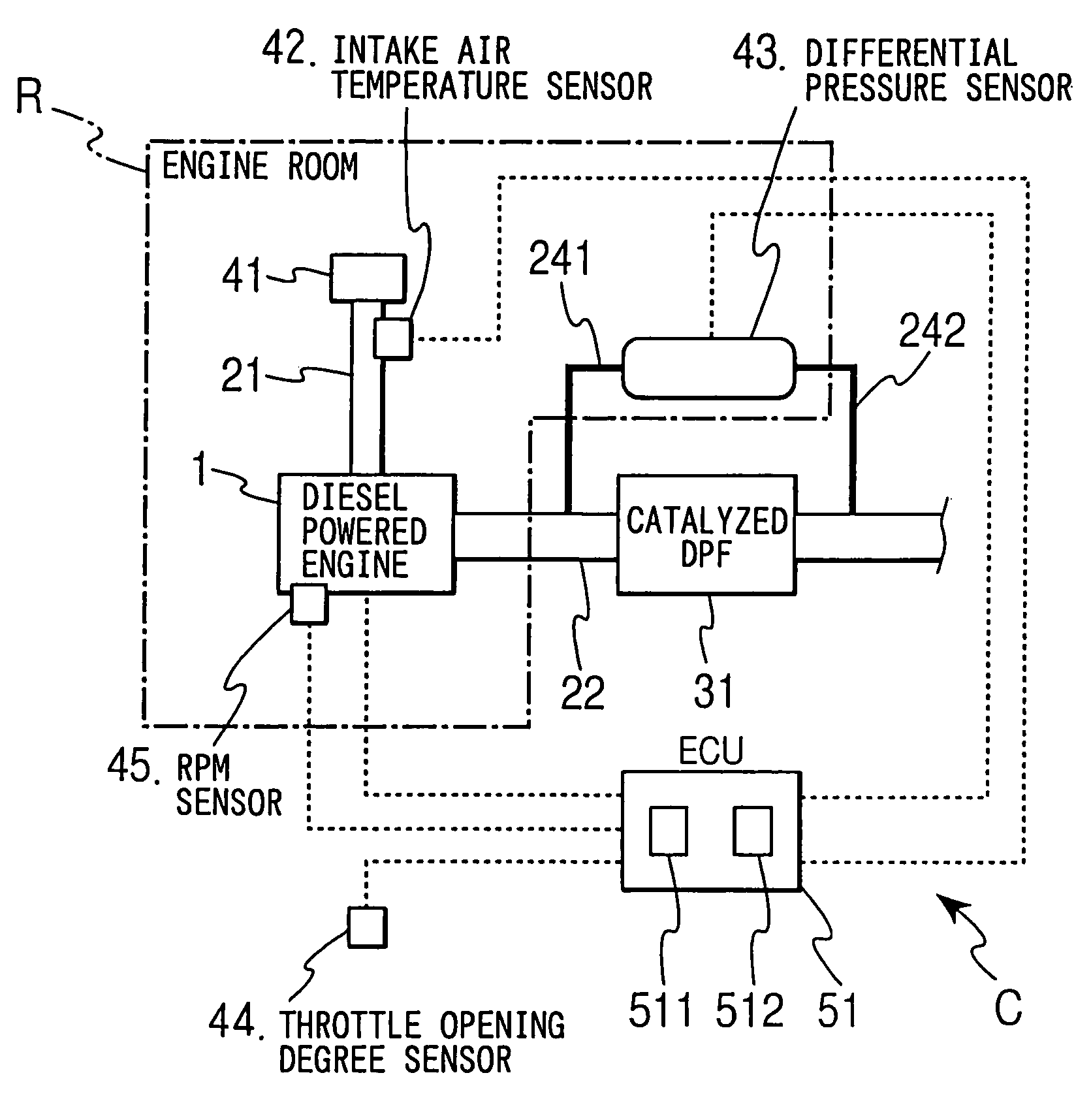
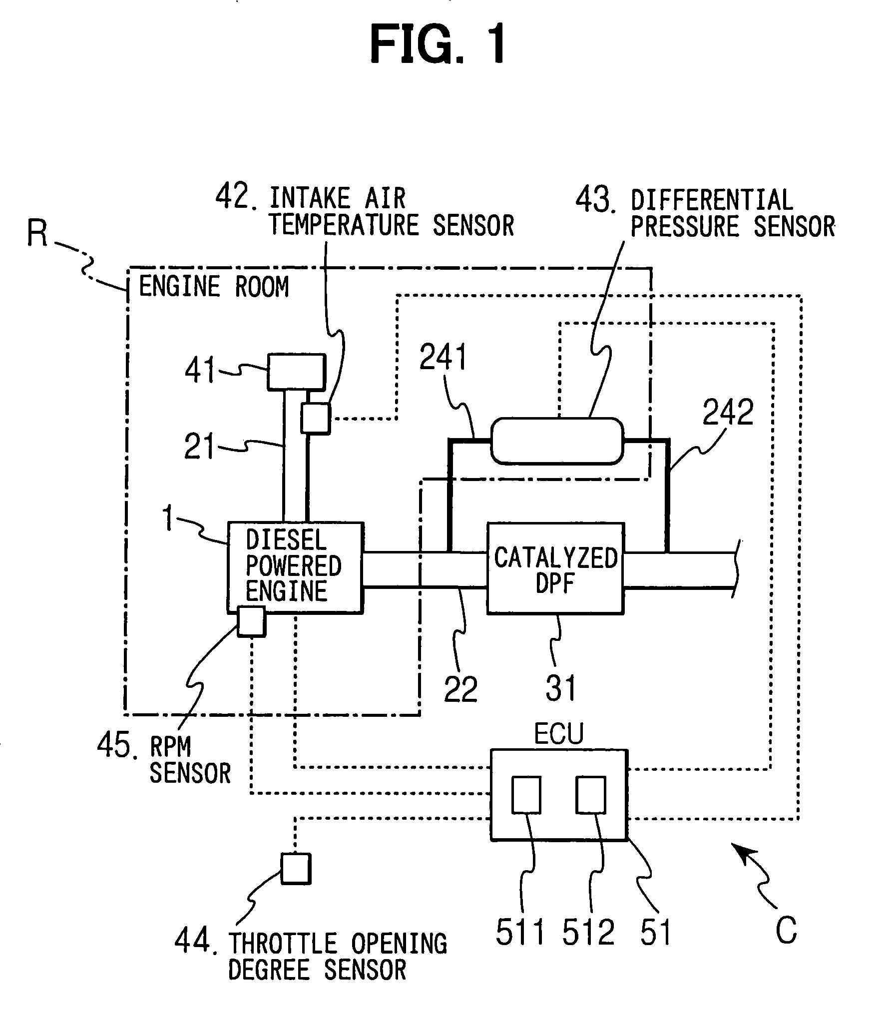
[0030]Preferred embodiments of the invention will be hereinafter described with reference to the accompanying drawings. FIG. 1 shows the overall structure of a diesel powered engine system equipped with the exhaust emission control device according to the invention. A catalyzed diesel particulate filter carrying an oxidation catalyst (hereinafter “catalyzed DPF”) 31 is disposed in an exhaust passage 22 of the engine 1, as an exhaust treatment device. The catalyzed DPF 31 is made of heat resistant ceramic such as cordierite in a honeycomb structure that has multiple cells forming gas passages opened at one end and closed at the other end so that the passages are alternately closed at each end. An oxidation catalyst such as Pt is coated on the cell wall surface. The exhaust from the engine 1 flows downstream through porou...


PUM


Abstract

An engine exhaust emission control device determines a differential pressure across a diesel particulate filter (DPF) to enable regeneration of the DPF at optimal timing. An ECU estimates the temperature of a differential pressure sensor provided for the DPF from the output of an intake air temperature sensor when the engine is not running, and determines an offset correction factor for correcting the sensor's offset error. The factor is set using the sensor output at this time as sensor's offset error, and stored in a memory. When detecting the differential pressure across the DPF, the temperature of the sensor at this time is estimated, and an offset correction factor that corresponds to this estimated temperature is selected. The sensor outputs are adjusted with this offset correction factor.

Description

CROSS REFERENCE TO RELATED APPLICATIONS[0001]This application is based upon, claims the benefit of priority of, and incorporates by reference Japanese Patent Application No. 2003-35276 filed Feb. 13, 2003.BACKGROUND OF THE INVENTION[0002]1. Field of the Invention[0003]The present invention relates to an exhaust emission control device for purifying exhaust from internal combustion engines by trapping exhaust particulates.[0004]2. Description of the Related Art[0005]Emission control requirements for internal combustion engines of automobiles are becoming increasingly stringent. Emission reduction of CO, HC, NOX and particulates such as soot and SOF contained in the exhaust is particularly required for compression-ignition (diesel cycle) engines that are fueled by diesel fuel. To trap particulate matter (PM) in the exhaust from diesel powered engines, a diesel particulate filter (DPF) is normally disposed in the exhaust passage. A DPF is regenerated by periodic oxidation of accumulate...

Claims


Application Information

Patent Timeline
IPC IPC(8): F01N3/00F01N3/02F02D45/00F01N9/00F02D41/02F02D41/24F02D41/38
CPCF01N9/002F02D41/029F02D41/1448F02D41/2441F02D41/2474F02D41/28F01N9/005Y02T10/47F01N2330/06F01N2430/08F01N2430/085F01N2510/065F02D41/187F02D41/3827F02D2041/1422F02D2200/0404F02D2200/0414F02D2200/0812Y02T10/40
Inventor KUBOSHIMA, TSUKASAOKUGAWA, SHINICHIROBABA, HIRONOBU
Owner DENSO CORP
Why Eureka
Try Eureka