Controller

a controller and controller technology, applied in the field of controllers, can solve the problems of delay in motion of the machine, low rigidity of the machine, and vibration of the movable part of the machine, and achieve the effect of suppressing the delay of motion of the movable part and reducing the vibration caused by the delay

Active Publication Date: 2006-04-18
FANUC LTD
View PDF26 Cites 45 Cited by
  • Summary
  • Abstract
  • Description
  • Claims
  • Application Information

AI Technical Summary

Benefits of technology

[0008]When a machine element having low rigidity is situated in between a movable part of a machine and a motor for driving the movable part and a command is given to the machine to move the movable part, the present invention suppresses a delay of motion of a machine's movable part which is caused by torsion, or the like, of the machine element between the movable part of the machine and a motor for driving the movable part. By suppressing a delay of motion of a machine part, vibrations caused by the delay are reduced.
[0010]According to one aspect of the present invention, the controller comprises: velocity command determining means for obtaining a compensated velocity command for the velocity loop control by adding a velocity offset amount proportional to a command acceleration to the velocity command outputted by the position loop control; torque offset calculation means for calculating a torque offset amount based on a differentiated value of the velocity offset amount; and torque command determining means for obtaining a compensated torque command for the servomotor by adding the torque offset amount to a torque command outputted by the velocity loop control performed based on the compensated velocity command. With the above arrangement, the torsion of the machine is compensated to reduce a response delay and also suppress the vibrations. Additionally, the velocity offset amount may be a sum of an offset amount proportional to a command velocity and an offset amount proportional to the command acceleration.

Problems solved by technology

Machines of a large size are generally subject to torsion, or a similar force, in a machine element located in between a motor for driving a machine's movable part and the machine's movable part, thereby causing the machine to have low rigidity.
In this case, motion of the machine is delayed at the start of the machine motion, and the delay generates vibrations of the machine's movable part.
In such a large-scaled machine, a large position gain of a position loop can not be adopted in view of suppressing the vibrations of the machine's movable part, resulting in the delay in motion of the machine's movable part.
For example, a machine tool of large size has a problem that the delay lowers its machining accuracy.

Method used


Image

  • Controller
  • Controller
  • Controller

Examples


first embodiment

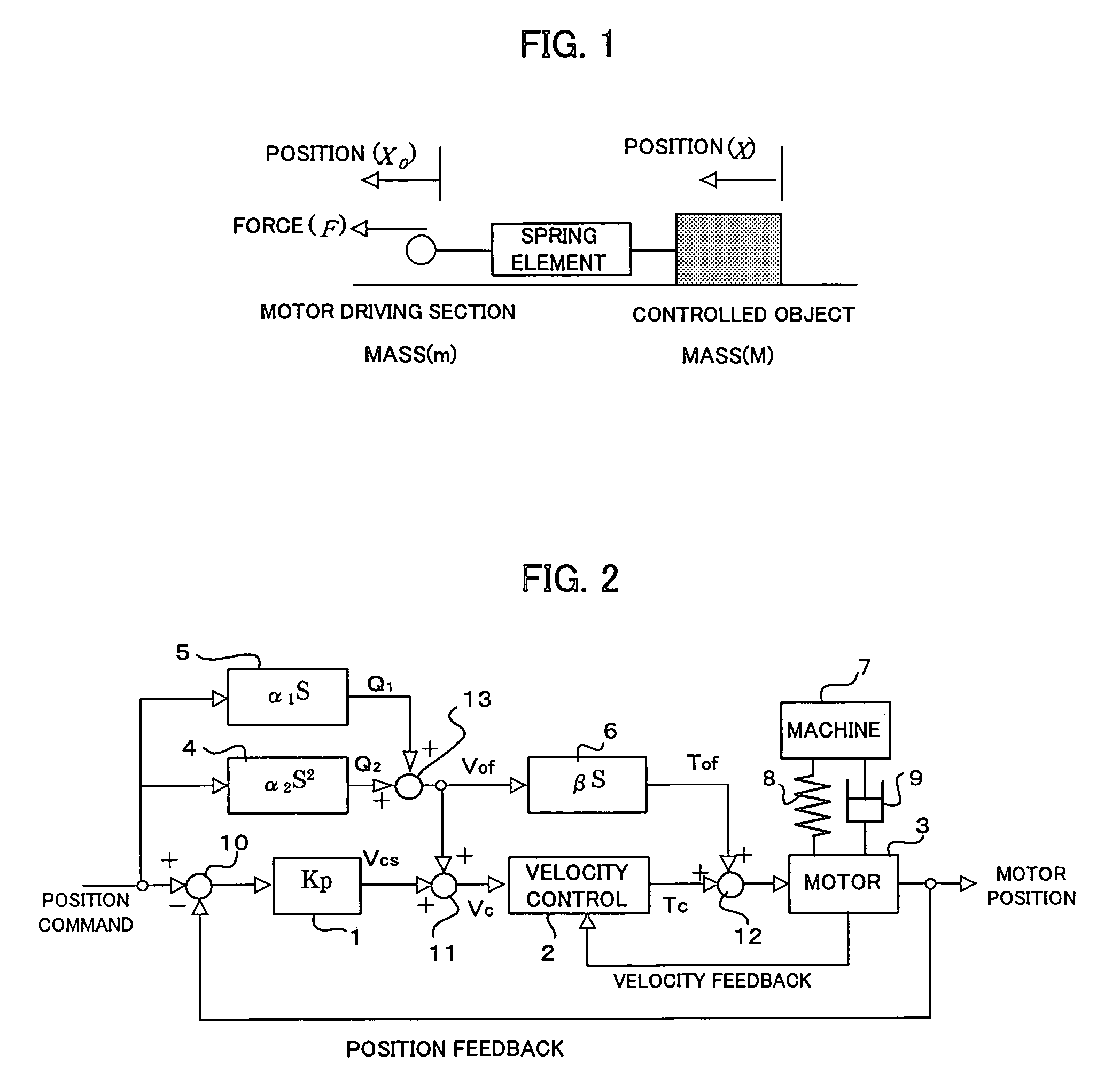
[0037]FIG. 2 is a block diagram showing a motor control system of a controller for controlling a position of a machine's movable part according to the present invention.

[0038]In FIG. 2, reference numeral 1 represents a term indicating a transfer function of a position gain Kp in the position loop, reference numeral 2 represents a term of a velocity control section, and reference numeral 3 represents a servomotor. Connected to the servomotor 3 is a movable part of a machine 7, such as a machine tool and the like. On condition that the servomotor 3 and the machine are connected to each other using an element having low rigidity, the drawing illustrates the connection utilizing a spring 8 in the form of a diagram. Additionally, reference numeral 9 denotes a term of friction.

[0039]In this embodiment, a term 4 is provided for predicting the torsion of the machine element having low rigidity, (the machine element being located in between the machine and the servomotor and shown, for examp...

second embodiment

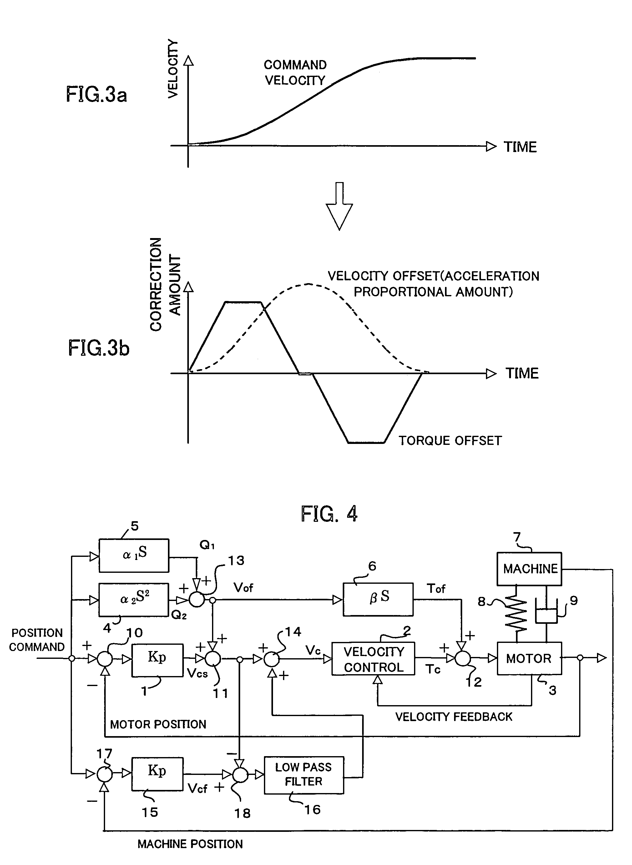
[0048]FIG. 4 is a block diagram showing a motor control system according to the present invention.

[0049]The second embodiment is different from the first embodiment in that the full-closed loop control of the position is added.

[0050]In the second embodiment, a position deviation between the position command and the machine position that is feedbacked from the position detector for detecting the position of the machine's movable part is obtained by using a subtracter 17. The position deviation is multiplied by the position gain Kp (having the same value as the position gain in the term 1) in a term 15 to obtain the velocity command Vcf. The velocity command, that is compensated by adding the velocity offset amount Vof to the velocity command Vcs obtained in the semi-closed loop control, is subtracted from the velocity command generated by the full-closed loop control utilizing a subtracter 18, thereby passing the result through a lowpass filter 16. The output of a low frequency compo...

third embodiment

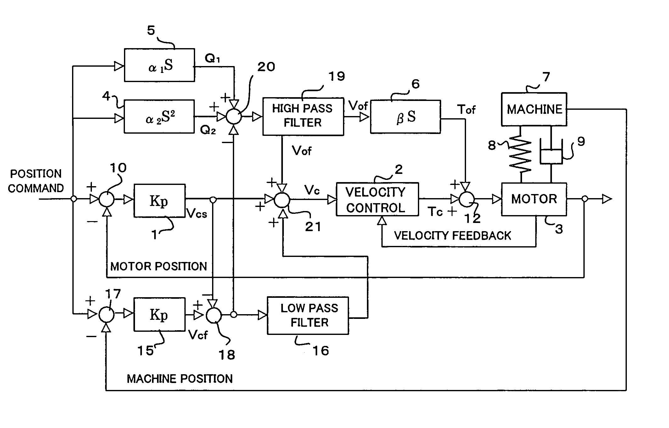
[0056]FIG. 5 is a block diagram showing a motor control system according to the present invention.

[0057]In the third embodiment, similarly to the second embodiment, the semi-closed and the full-closed loop control of the position are performed.

[0058]The velocity command Vcs outputted from the term 1 by the semi-closed loop control of the position is subtracted from the velocity command Vcf outputted from the term 15 by the full-closed loop control of the position using the subtracter 18 to obtain an amount corresponding to an actual torsion amount.

[0059]An adder / subtracter 20 performs a calculation of subtracting the amount corresponding to the actual torsion amount from the amount corresponding to the estimated torsion amount obtained by adding an amount Q2 proportional to acceleration of the position command, that is the output of the term 4, and an amount Q1 corresponding to the friction 9 of the machine, that is the output of the term 5. The result of the calculation is passed t...


PUM


Abstract

A controller capable of preventing response delay and generation of vibrations attributable thereto during position control of a movable part of a machine having low rigidity. A motor for driving a machine having low rigidity is subjected to position and velocity loop control. Compensation amount Q1 proportional to command velocity obtained by differentiating a position command and compensation amount Q2 proportional to second-order differentiated command acceleration are obtained. Compensation amounts Q1 and Q2 are added together, thus obtaining a velocity offset amount Vof corresponding to a estimated torsion amount. A differentiated value of the velocity offset amount is multiplied by coefficient β to obtain a torque offset amount Tof. The velocity offset amount Vof is added to a velocity command Vcs obtained by position loop control 1. The torque offset amount Tof is added to a torque command Tc outputted in velocity loop control 2, and the result is used as a drive command to the motor. Based on the velocity and the torque offset amount Vof and Tof, a torsion amount between motor 3 and the machine is controlled. The machine position and velocity are controlled with accuracy by regular position and velocity loop control.

Description

BACKGROUND OF THE INVENTION[0001]1. Field of the Invention[0002]The present invention relates to a controller for controlling a position of a movable part of a machine by a servomotor.[0003]2. Description of Related Art[0004]Machines of a large size are generally subject to torsion, or a similar force, in a machine element located in between a motor for driving a machine's movable part and the machine's movable part, thereby causing the machine to have low rigidity. When the machine has low rigidity, the torsion element, or the similar force, has characteristics similar to a spring in which a torsion amount becomes larger in proportion to acceleration within a certain range. In some cases, the motor and the machine are connected to each other by spring engagement, or other possible similar connections. In this case, motion of the machine is delayed at the start of the machine motion, and the delay generates vibrations of the machine's movable part.[0005]In such a large-scaled machin...

Claims


Application Information

Patent Timeline
Patent Type & Authority Patents(United States)
IPC IPC(8): G05B19/18G05B19/19B23Q15/013G05B11/32G05B19/31G05B19/39G05B19/404G05D3/12H02P29/00
CPCG05B19/39G05B19/404G05B2219/41251G05B2219/41445G05B2219/41421G05B2219/41431G05B2219/41408
Inventor IWASHITA, YASUSUKEKAWAMURA, HIROYUKI
Owner FANUC LTD
Why Eureka
Try Eureka