
Planar antenna and antenna system

a technology of antenna system and antenna, applied in the direction of antenna, antenna supports/mountings, coupling devices, etc., can solve the problems of reducing accuracy and disturbing measurement, and achieve the effect of improving the strength of the whole assembly

Inactive Publication Date: 2006-04-18
VEGA GRIESHABER GMBH & CO
View PDF6 Cites 81 Cited by
  • Summary
  • Abstract
  • Description
  • Claims
  • Application Information

AI Technical Summary

Benefits of technology

The invention is a planar antenna that can be used in a tube and is designed to use the TE01-mode. It solves the problems of using horn antennas in tubes and can be used at frequencies between 3 GHz and 70 GHz. The antenna has dipole arms arranged on the substrate in a perimeter of a circle with a predetermined radius. The dipole arms can be connected by a connection element, which is a shaped ring or a connection ring. The antenna can be easily manufactured and has a symmetrical field pattern. It can be used in a waveguide-tube and can be designed to have a high impedance at its center. The dipole arms can be bent according to the perimeter of the circle or straight lines. The invention provides a more efficient and symmetrical solution for exciting the TE01-mode in a tube.

Problems solved by technology

Horn antennas and the use of the fundamental TE11-mode allow high resolution and high accuracy, but there are limitations due to the influence of the wall material of the measuring pipes.
The bypass holes may cause false echoes, disturb the measurement and may decrease the accuracy.

Method used


Image

  • Planar antenna and antenna system
  • Planar antenna and antenna system
  • Planar antenna and antenna system

Examples


second embodiment

[0056]In FIG. 9, several various embodiments of an antenna system according to the invention are shown. For simplification of the drawings, only the substrate 6 and the waveguide-tube 2 are shown. In the first exemplary embodiment of the invention, a covering layer 40 is provided directly on the substrate 6. The covering layer 40 is of a dielectric material. In the second embodiment, a covering layer 41 is arranged at a distance to the substrate 6. The third and fourth exemplary embodiments show a covering layer 42, 43 arranged at a distance to the substrate 6 but having a convex or conical shape.

sixth embodiment

[0057]The fifth and sixth embodiment of the present invention show a covering layer 44 and 45 arranged on the substrate 6. Again, the covering layers 44, 45 have a conical or convex shape.

[0058]The last embodiment comprises a covering layer 46 including two or more different layers 46a, 46b. The outer layer 46b has a convex or concave shape.

[0059]The material of the covering layer has to be a dielectric material, as, for example, PTFE. The thickness of such a layer may be approximately λ / 4 or n×λ / 4, wherein n∈N.

[0060]Finally, we refer to FIG. 10 showing a schematic cross section of an antenna system 1 according to the present invention. Here, the planar antenna 5 is arranged as mentioned above within the waveguide-tube 4. A bypass-tube 45 is connected with the waveguide-tube 4 by a taper 44. The taper serves to match the inventive antenna system 1 with the bypass-tube 45 having a diameter larger than the diameter of the waveguide-tube 4.

[0061]If the diameter of the bypass-tube 45 ha...


PUM


Abstract

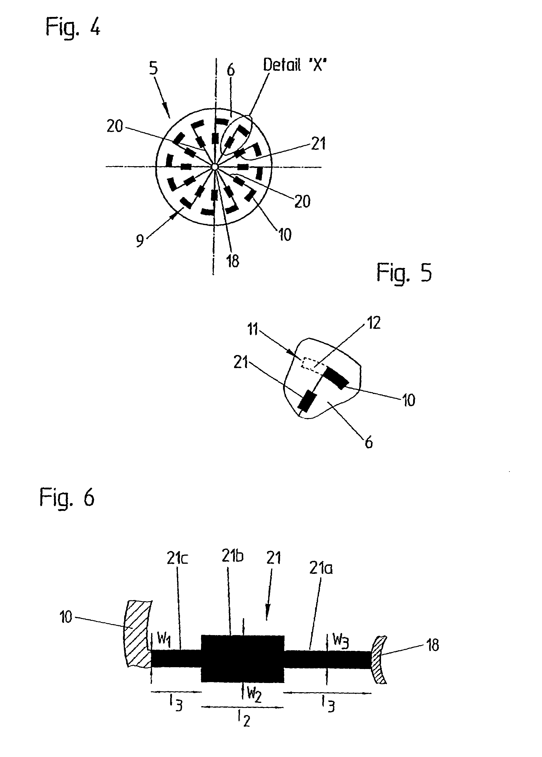
The present invention relates to a planar antenna (1) for excitation of the TE01-mode of an electromagnetic wave and adapted to be arranged in a waveguide tube (2). The planar antenna comprises a substrate (6) of dielectric material having a first surface (7) intended to face towards a filling good surface and a second surface (8) facing in an opposite direction. A first group (9) of a plurality of dipole arms (10) is arranged on the first surface (7) or the second surface (8) on a perimeter of a circle with a predetermined radius. A second group (11) of a plurality of dipole arms (12) is arranged on the first surface (7) or the second surface (8) on the perimeter of the circle with the predetermined radius. The dipole arms (10) of the first group (9) extend in a first direction and the dipole arms (12) of the second group (11) extend in a direction opposite the first direction. Furthermore, the present invention relates to an antenna system comprising a cylindrical waveguide tube (2) having a bottom plate (3) and a tube portion (4) and a planar antenna (1) as mentioned above.

Description

CROSS-REFERENCE TO RELATED APPLICATIONS[0001]This application is a continuation under 35 U.S.C. 111(a) of PCT / EP03 / 05118, filed May 15, 2003, and published in English on Nov. 27, 2003 as WO 03 / 098168 A1, which claimed priority under 35 U.S.C. 119(e) of U.S. Provisional Application Ser. No.: 60 / 381,235, filed May 16, 2002, which applications and publication are incorporated herein by reference.FIELD OF THE INVENTION[0002]The invention relates to a planar antenna for exciting the TE01-mode (also known as H01-mode) and intended to be used in a filling level measuring device for determining a filling height of a filling good in a receptacle. The present invention relates furthermore to an antenna system adapted to be used in a tube, e.g. a bypass tube, for measuring the height of a filling good in a receptacle.[0003]The “genuine radar method” (also called pulse radar method) and the “time domain reflectometry (TDR)-Method” generate electromagnetic waves or measuring signals which are tr...

Claims


Application Information

Patent Timeline
Patent Type & Authority Patents(United States)
IPC IPC(8): H01Q13/00H01Q9/28H01P5/10H01Q1/22H01Q1/38H01Q9/06H01Q13/06H01Q13/18H01Q21/06H01Q21/20
CPCH01P5/10H01Q1/225H01Q21/20H01Q9/285H01Q21/062H01Q9/065
Inventor MAHLER, WOLFGANGLANDSTORFER, FRIEDRICHMOTZER, JURGEN
Owner VEGA GRIESHABER GMBH & CO
Learn More