Shapable antenna beams for cellular networks

a technology of cellular networks and antenna beams, applied in the direction of antennas, climate sustainability, sustainable buildings, etc., can solve the problems of increased interference experienced with respect to a user's signal of interest, increased communication system capacity and communication quality, and inability to meet the needs of users, etc., to improve service quality, increase communication capacity, and increase communication capacity

Inactive Publication Date: 2006-04-18
F POSZAT HU
View PDF8 Cites 21 Cited by
  • Summary
  • Abstract
  • Description
  • Claims
  • Application Information

AI Technical Summary

Benefits of technology

[0011]The present invention is directed to a system and method which substantially equalizes communication system service area boundaries to thereby provide a substantially uniform communication condition throughout such service areas. Implementing aggressive cell sculpting according to the present invention, preferred embodiments change a cell footprint to provide a desired cell boundary in response to cell topology and / or morphology features. Preferably, aggressive cell sculpting according to the present invention remediates radial variance of signal communication within a cell, e.g., variance of communication conditions throughout various degrees of azimuth, to thereby provide increased communication capacity and / or improved quality of service. Moreover, implementation of preferred embodiments of the present invention includes careful cell planning to provide load balancing to increase communication capacity and / or improve quality of service.

Problems solved by technology

As wireless communications become more widely used, the number of individual users and communications multiply and, thus, communication system capacity and communication quality become substantial issues.
For example, an increase in cellular communication (e.g., cellular telephony, personal communication services (PCS), and the like) utilization results in increased interference experienced with respect to a user's signal of interest due to the signal energy of the different users on the cellular system.
Such interference is inevitable because of the large number of users and the finite number of cellular communications cells (cells) and frequency bands, time slots, and / or codes (channels) available.
However, despreading of the desired communication unit's signal results in the receiver not only receiving the energy of this desired signal, but also a portion of the energies of other communication units operating over the same frequency band.
Accordingly, as the number of users utilizing a CDMA network increases, interference levels experienced by such users increase.
Accordingly, the quality of service (QOS) of communications and the capacity of the communication network are typically substantially impacted by interference or noise energy.
For example, CDMA systems are interference limited in that the number of communication units using the same frequency band, while maintaining an acceptable signal quality, is determined by the total energy level within the frequency band at the receiver.
For example, topological characteristics (mountains, valleys, etc.) and / or morphological characteristics (large buildings, different building heights, shopping centers, etc.) result in different path losses experienced in different azimuthal directions from the BTS.
However, because of the irregular boundaries experienced in actual cell implementations (e.g., path loss variance), a user moving about a cell and even a sector may experience a wide variety of communication conditions, including outage conditions (e.g., Ec / No≧−15 dB) or poor quality of service.
For example, this user may move only a few degrees in azimuth with respect to a BTS and experience significant signal quality degradation.
Accordingly, this user may experience unacceptable communication conditions, such as the aforementioned outage conditions, when noise or interference levels are otherwise generally within acceptable limits for operation within the network.
Both the user's signal of interest, such as a serving pilot signal, and interference associated therewith are typically subject to log-normal shadowing.
It can therefore be appreciated that the capacity of the cell may be unnecessarily limited and / or the quality of communications provided thereby may be substandard if the quality of various signals of interest with respect to individual users is not maintained and / or interference energy is not controlled.

Method used


Image

  • Shapable antenna beams for cellular networks
  • Shapable antenna beams for cellular networks
  • Shapable antenna beams for cellular networks

Examples


Embodiment Construction

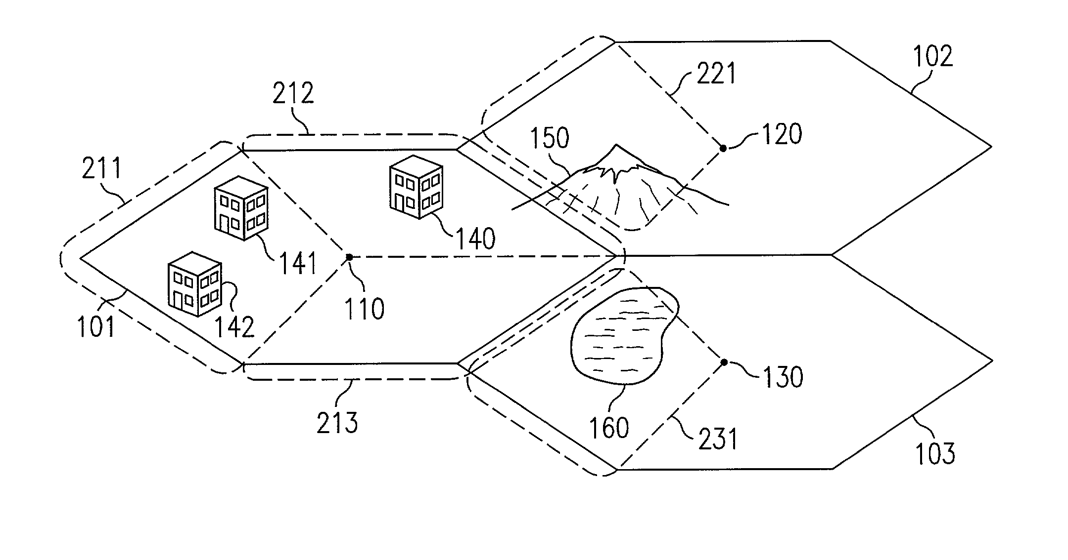
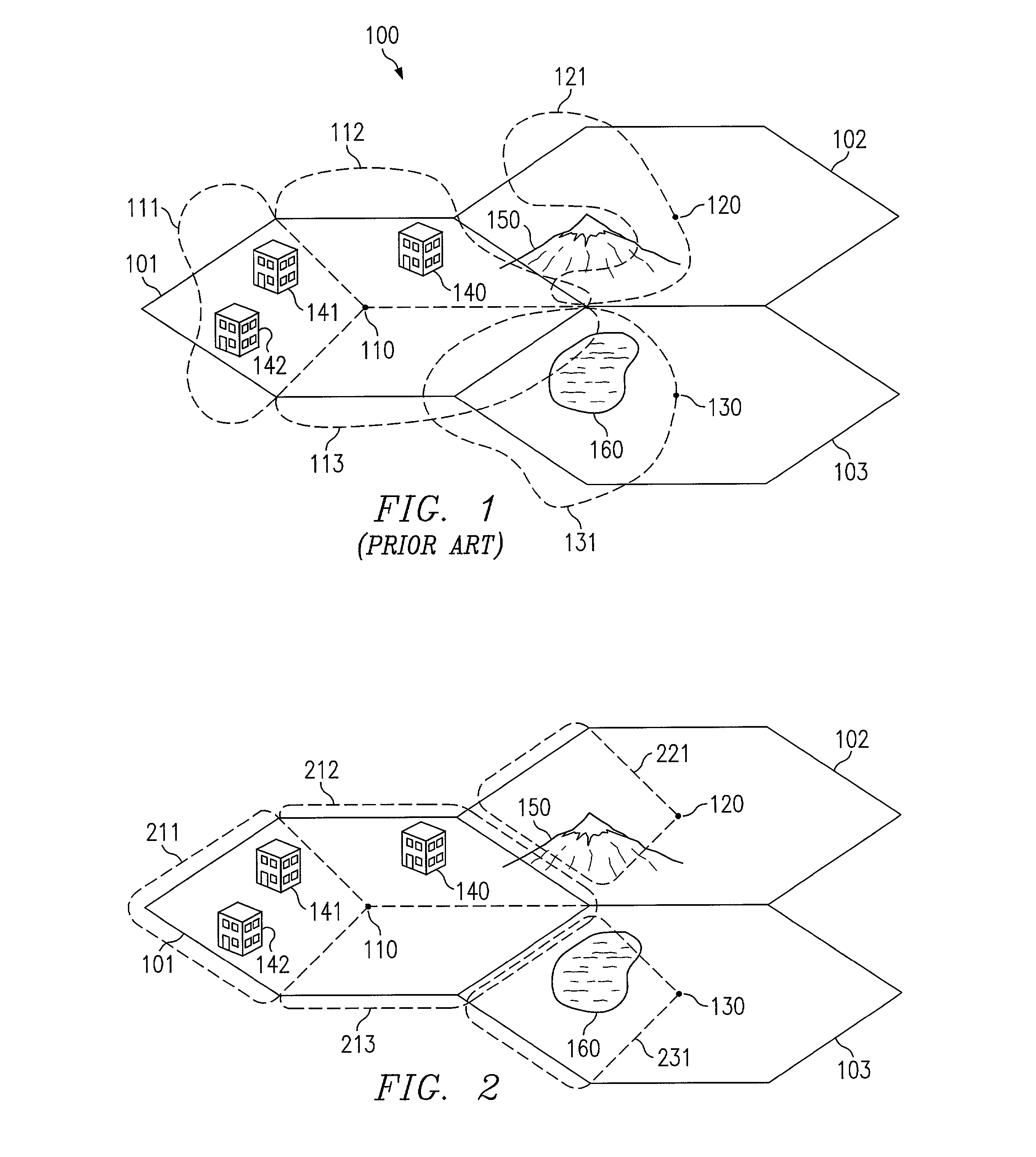
[0031]As illustrated in FIG. 1, cellular communications systems have typically been conceptualized for analysis and planning purposes as a grid of hexagonal areas (cells) of substantially equal size disposed in a service area. For example, cells 101, 102 and 103 of FIG. 1 are identified with the areas of communication associated with base transceiver stations (BTSs) 110, 120, and 130, respectively. Accordingly, service area 100 is provided communication services throughout by “honeycombed” deployment of such cells.

[0032]However, the communication coverage associated with a BTS may vary substantially from the theoretical boundaries of the hexagonal cell due to cell topology and morphology. For example, as shown in FIG. 1 cell 101 includes morphological features disposed therein. Accordingly, sector 112, having building 140 disposed therein, presents a contour appreciably different than the cell boundary the sector theoretically follows due to signal fading and / or shadowing associated...


PUM


Abstract

Systems and methods are disclosed which provide aggressively sculpted or shaped antenna beams, such as sector antenna beams, for use in communication networks. Preferred embodiments use passive antenna feed networks, preferably configured as personality modules, which are adapted for corresponding topological and morphological features. Preferred embodiment feed networks may be coupled to linear or curvilinear antenna arrays to provide antenna beams having a desired contour. Using the disclosed systems and methods path loss variance is minimized for improved system capacity and/or signal quality. Moreover, the disclosed systems and methods provide for reduced average transmission power levels further allowing increased capacity and/or signal quality.

Description

RELATED APPLICATIONS[0001]The present application is related to the following co-pending and commonly assigned U.S. patent applications Ser. No. 09 / 384,306 entitled “Antenna Deployment Sector Cell Shaping System and Method,” filed Aug. 26, 1999, which is a continuation-in-part of Ser. No. 08 / 924,285 entitled “Antenna Deployment Sector Cell Shaping System and Method,” filed Sep. 5, 1997, which itself is a continuation-in-part of Ser. No. 08 / 786,725 entitled “Antenna Deployment Sector Cell Shaping System and Method,” filed Jan. 27, 1997; serial number [47586-P032C1-10101919] entitled “Dual Mode Switched Beam Antenna,” filed Mar. 2, 2001, which is a continuation of Ser. No. 09 / 213,640, now U.S. Pat. No. 6,198,434, entitled “Dual Mode Switched Beam Antenna,” filed Dec. 17, 1998; and Ser. No. 09 / 618,088 entitled “Base Station Clustered Adaptive Antenna Array,” filed Jul. 17, 2000; the disclosures of all of which are hereby incorporated herein by reference.TECHNICAL FIELD[0002]The inventi...

Claims


Application Information

Patent Timeline
Patent Type & Authority Patents(United States)
IPC IPC(8): H04B1/38H04W16/00H04W16/24
CPCH04W16/00Y02B60/50H04W16/24
Inventor SCHERZER, SHIMON B.GORDON, SCOT D.MARTEK, GARY A.RAMAKRISHNA, DEEPA
Owner F POSZAT HU
Why Eureka
Try Eureka