Current limit with adaptive cycle skipping for switching regulators

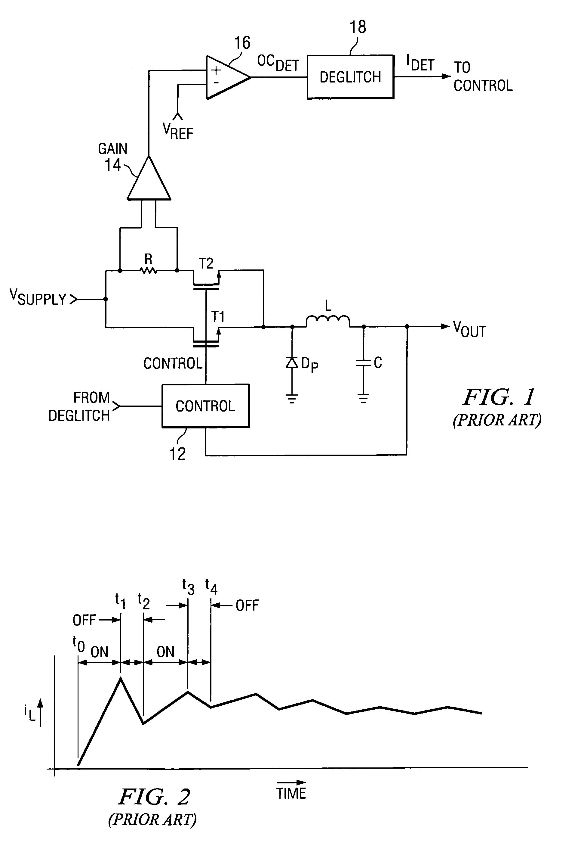
a switching regulator and current limit technology, applied in adaptive control, process and machine control, instruments, etc., can solve problems such as poor control of output current, catastrophic failure of load circuit, and delay in detecting overload or short circuit in prior art regulators such as the one shown in fig. 1

Active Publication Date: 2006-04-25
TEXAS INSTR INC
View PDF1 Cites 41 Cited by
  • Summary
  • Abstract
  • Description
  • Claims
  • Application Information

AI Technical Summary

Benefits of technology

[0010]The present invention provides a solution to the aforementioned problems, and provides a switching regulator having a current limit with adaptive cycle skipping. A buck type switching regulator circuit is provided, including an energy storage component, such as an inductor or capacitor, and a switch for controllably providing an input current to the energy storage component. A control unit controls the on time and the off time of the switch by providing cyclically recurring control pulses to the switch that cause the switch to be on during the pulses and off otherwise. A current monitor circuit monitors a current corresponding to t

Problems solved by technology

Prior art regulators such as the one shown in FIG. 1 may not have the capability of detecting an overload or short circuit in the load.
However, supplying more power during a short circuit or overload condition may result in a catastrophic failure of the load circuit, and of the regulator circuit, as well
While cycle skipping provides some protection in overcurrent cond

Method used


Image

  • Current limit with adaptive cycle skipping for switching regulators
  • Current limit with adaptive cycle skipping for switching regulators
  • Current limit with adaptive cycle skipping for switching regulators

Examples


Embodiment Construction

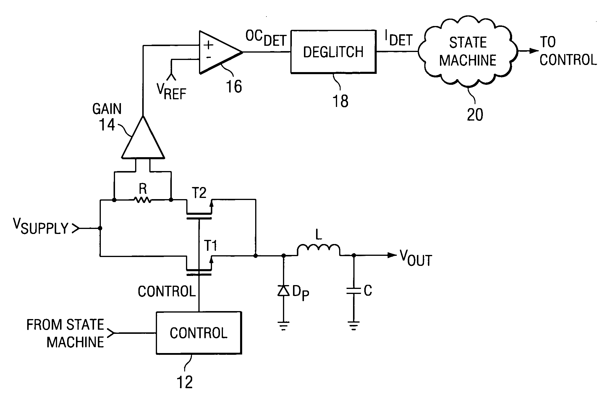
[0016]The present invention provides a switching regulator having an open-loop, digital overcurrent control system. The overcurrent control system of the present invention is capable of regulating the output current of the regulator below the desired level in both hard-short and soft-short conditions, and allows start-up even in soft short conditions. It is applicable to any switching regulator having buck functionality, such as a buck regulator or a buck-boost regulator, of which numerous configurations are known in the art.

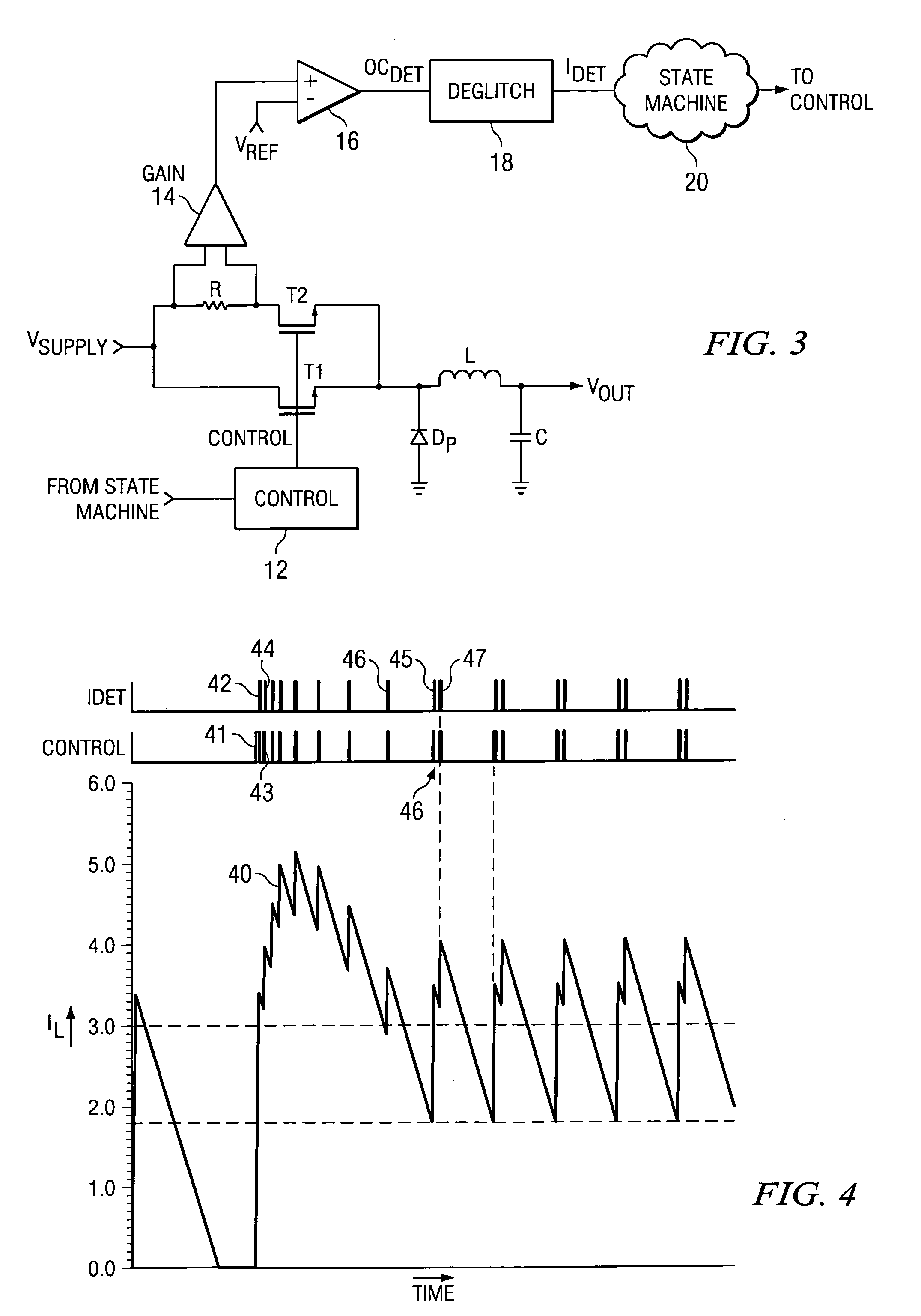
[0017]FIG. 3 is a diagram of a preferred embodiment of the present invention. In this embodiment, a dynamic cycle-skipping system is provided that adjusts the duty cycle adaptively to prevent the inductor current from running away. This embodiment is similar to that of FIG. 1, with the exception that a state machine 20 is provided, that implements an algorithm according to the principles of the present invention. Components in FIG. 3 that are the same as those i...


PUM


Abstract

A switching regulator having a current limit with adaptive cycle skipping. A buck type switching regulator circuit is provided, including an energy storage component, such as an inductor or capacitor, and a switch for controllably providing an input current to the energy storage component. A control unit controls the on time and the off time of the switch by providing cyclically recurring control pulses to the switch that cause the switch to be on during the pulses and off otherwise. A current monitor circuit monitors a current corresponding to the input current applied to the energy storage component during the periodic control pulses. An overcurrent signal generator generates an overcurrent signal pulse upon detection of the monitored current at a level above a predetermined level corresponding to an overcurrent condition. A state machine responds to the overcurrent signal pulse and suppresses a number of the cyclically recurring control pulses, thereby controlling the period between the recurring control pulses that are not suppressed, in accordance with a predetermined algorithm that increases the number each time an overcurrent signal pulse is detected in successive periods.

Description

TECHNICAL FIELD OF THE INVENTION[0001]The present invention relates to switching power supply regulators, and more particularly relates to overcurrent detection in buck type regulators.BACKGROUND OF THE INVENTION[0002]Switching power supply regulators are widely used in the electronic arts, for example in battery management, because of their high efficiency. Such regulators convert a DC source at a reference voltage to a DC supply at a different voltage. The switching regulator uses an inductor, a transformer or a capacitor as an energy storage element to transfer energy from source to supply in discrete packets, defined by the ON and OFF times of a typically fixed frequency control signal CTL that controls the state of a switch. Feedback circuitry is typically used to maintain the supply voltage substantially constant, by adjusting the amount of ON time in accordance with load demands. One type of switching regulator is the buck regulator, which provides a DC supply voltage that is...

Claims


Application Information

Patent Timeline
IPC IPC(8): H02H9/08
CPCH02M3/157H02H9/025
Inventor TIEW, KEE CHEESCHMIDT, THOMAS A.SMITH, BRETT E.VOGT, JOHN C.RAHMAN, ABIDUR
Owner TEXAS INSTR INC
Why Eureka
Try Eureka