Apparatus for heat transfer and critical heat flux enhancement

a technology of critical heat flux and apparatus, applied in lighting and heating apparatus, semiconductor/solid-state device details, laminated elements, etc., can solve the problems of reducing the efficiency of heat removal, so as to increase the liquid velocity and increase the subcooling effect. , the effect of increasing the flow ra

Inactive Publication Date: 2006-04-25
MUDAWAR THERMAL SYST
View PDF8 Cites 64 Cited by
  • Summary
  • Abstract
  • Description
  • Claims
  • Application Information

AI Technical Summary

Benefits of technology

[0023]Published studies point to (1) increasing liquid velocity, (2) increasing subcooling, and/or (3) surface enhancement (i.e., incorporating surface fins) as three effective methods for delaying CHF. However, delaying CHF is sometimes realized with cooling system penalties. For example, large liquid velocities require large flow rates and...

Problems solved by technology

Such coolant flows can produce extreme pressure drops, which necessitate the use of specialized powerful pumps.
The challenge in cooling emerging and future devices and systems is to remove enormous amounts of heat using compact, lightweight cooling hardware, low coolant flow rates and relatively low pressure drops.
This is a formidable challenge considering that such coolant conditions are typically incompatible with high-flux removal.
Heat removal from electrical-current-carrying devices poses many unique challenges.
Despite the many recent signal speed-enhancing breakthroughs in such areas as superconductivity, optical transmission, gallium arsenide semiconductors, and parallel processing, the ever increasing demand for greater signal speed has created major challenges to the manufacturers of both commercial and defense electronics.
These challenges are difficult to meet even with today's most cutting-edge cooling technologies.
In fact, heat removal has emerged as an obstacle to electronic packaging at all levels: device, multi-device module, and system.
Thermal management obstacles have also been compounded by the increased signal speed requiring shorter distances between devices in multi-device modules and a closer packaging of modules in a cooling system.
Air cooling is still widely used and will always be favored, where possible, over all other cooling techniques; but the poor thermal transport properties of air require forced circulation at speeds that often exceed upper accepted limits for noise and vibration.
Even with the finning and the increased air speed, air is not likely to handle the high heat fluxes projected for the next generation of devices while maintaining acceptable device temperatures.
However, the cooling effectiveness of fluorochemicals is quite inferior to that water, which explains why many high-flux and ultra-high-flux devices are cooled with water.
As the heat dissipation rate increases further, the bubble crowding and coalescence begin to restrict liquid access...

Method used


Image

  • Apparatus for heat transfer and critical heat flux enhancement
  • Apparatus for heat transfer and critical heat flux enhancement
  • Apparatus for heat transfer and critical heat flux enhancement

Examples


Embodiment Construction

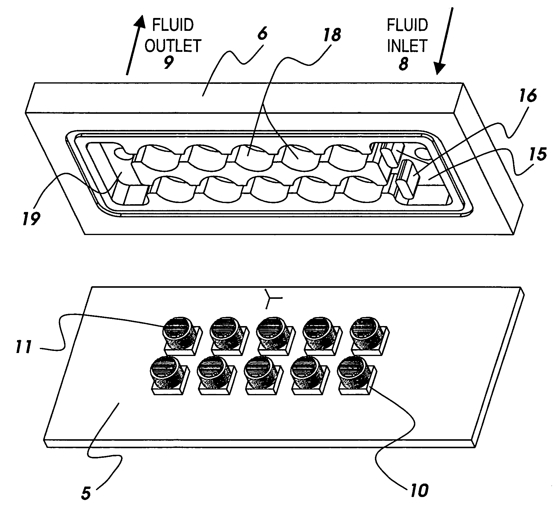
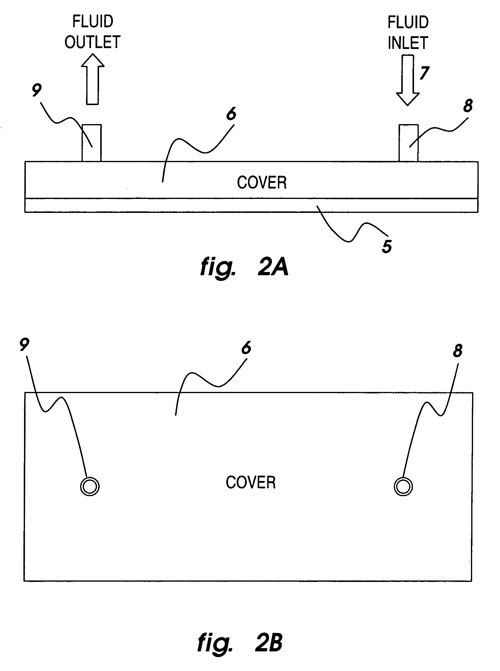
[0034]Heat dissipating devices 10 are embedded in the base plate 5 of the module illustrated in FIGS. 2A and 2B, and a cover plate 6 is used to introduce a liquid coolant 7 through an inlet port 8 into the module, to control coolant path within the module cavity, as well as to expel the coolant from the module through an outlet port 9. Different inlet and outlet configurations can be used with this module as illustrated in FIGS. 3A–3C. The coolant is conditioned by a flow loop external to the module (conditioning loop is not part of the present invention) that returns the coolant to the module at the appropriate temperature, pressure and flow rate.

[0035]Inside the module, the liquid extracts the heat from the devices 10 by turning partially into vapor through boiling. The liquid is supplied at the module inlet 8 in a subcooled state, i.e., at a temperature much lower than the liquid's boiling temperature corresponding to the inlet liquid pressure. This results in subcooled nucleate ...


PUM


Abstract

An apparatus for cooling single and multiple high-flux and ultra-high-flux heat dissipating devices, comprising a liquid coolant module having a base plate and a cover plate defining therebetween a liquid coolant chamber with a liquid coolant inlet port and a liquid coolant outlet port in fluid communication with the liquid coolant chamber; at least one heat dissipating device mounted to the liquid coolant module; a multi-level-cooling-enhancement stud mounted upon each heat dissipating device and disposed within the liquid coolant module; and apparatus for inducing phase change nucleate boiling of a subcooled liquid coolant within the liquid coolant module to enhance its cooling performance.

Description

[0001]The present application claims the benefits of now abandoned U.S. Provisional Patent Application No. 60 / 401,421, filed Aug. 6, 2002.[0002]This invention was made with Government support under contract DASG60-02-C-0050 awarded by U.S. Army Space and Missile Defense Command. The Government has certain rights in the invention.[0003]This invention concerns cooling systems for heat source devices that produce large amounts of heat from relatively small surface areas, and which rely upon the removal of the heat produced to maintain desired functionality.BACKGROUND OF INVENTION[0004]Breakthroughs in many of today's cutting-edge technologies are becoming increasingly dependent upon the ability to safely dissipate enormous amounts of heat from very small areas. A key measure of heat dissipation density is heat flux, or heat removal rate divided by heat dissipation area. Two ranges of device heat fluxes can be identified relative to the magnitude of the heat dissipation and the type of ...

Claims


Application Information

Patent Timeline
IPC IPC(8): H05K7/20F28F3/12H01L23/473
CPCF28F3/12H01L23/473F28D2021/0029H01L2924/0002H01L2924/00
Inventor MEYER, MICHAEL T.
Owner MUDAWAR THERMAL SYST
Why Eureka
Try Eureka