Method of manufacturing stator for brushless motors

Inactive Publication Date: 2006-05-02
PANASONIC CORP
View PDF17 Cites 17 Cited by
  • Summary
  • Abstract
  • Description
  • Claims
  • Application Information

AI Technical Summary

Benefits of technology

[0030]According to this method, productivity increases to “N” times comparing with a conventional method, and manufacturing cost decreases.
[0031]In an exemplary embodiment, a land for coupling is formed on a section stuck out from the printed circuit board, the section is formed by the split-line—non-straight-line—running thro

Problems solved by technology

However, in a case of arranging number of flat air-core coils on a printed circuit board, the increasing of number “S” incurs a higher manufacturing cost as well as more steps of processing.
As a result, expensive brushless motors of a poor productivity are effected in many cases.
This requires expensive cost of apparatus and blocks the mass-production of low cost brushless motors.
The eddy-current-loss and sliding-friction discussed above produce to

Method used


Image

  • Method of manufacturing stator for brushless motors
  • Method of manufacturing stator for brushless motors
  • Method of manufacturing stator for brushless motors

Examples


exemplary embodiment 1

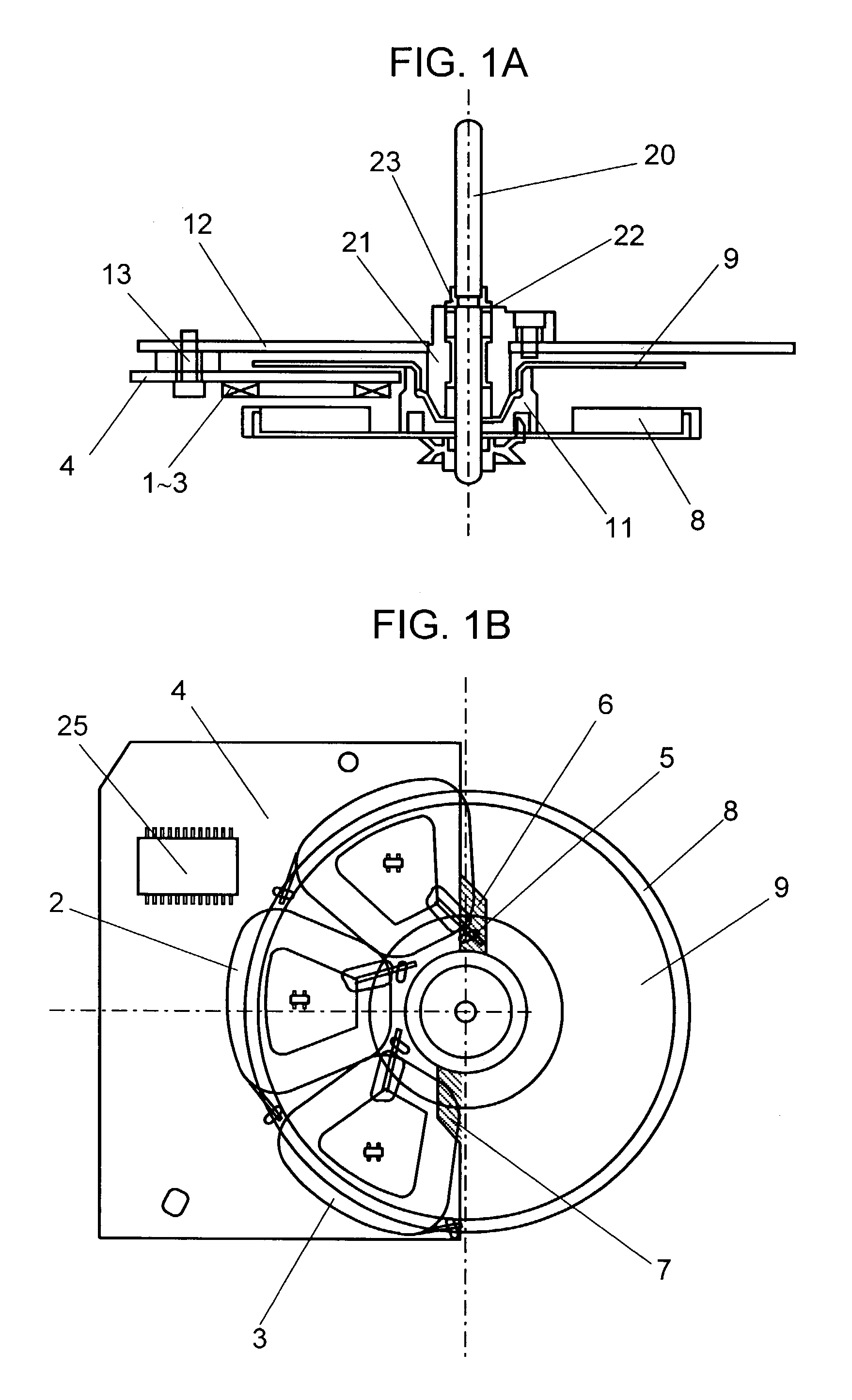
[0042]FIG. 1(a) and FIG. 1(b) are a cross section and a perspective view of a brushless motor of the present invention. In the cross section of FIG. 1(a), disc-shaped rotor 8 having a permanent magnet faces printed-circuit-board 4 on which coils 1–3 of respective 3 phases, i.e. total 3 pieces of coils, are bonded. On the other side of the coils, disc-shaped yoke 9 made of soft magnetic material is arranged. Yoke 9 is coaxial with disc-shaped rotor 8 and has an area equal to or more than the area the permanent magnet occupies.

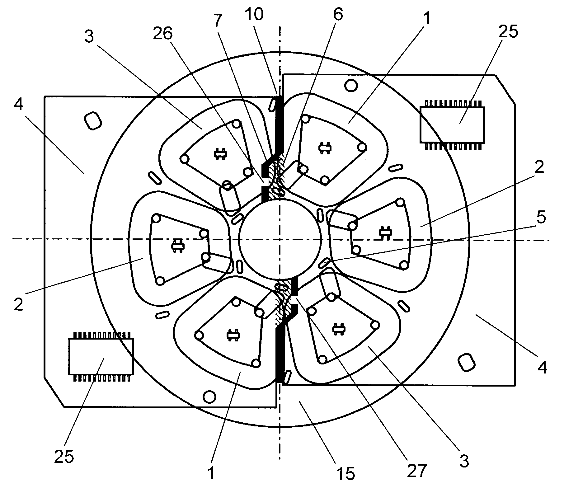
[0043]The perspective view of FIG. 1(b) illustrates the brushless motor of the present invention viewed from disc-shaped rotor 8 perspectively through respective components. Coils 1–3 and printed circuit board 4 are arranged within an area spanning 180 degree with regard to a rotary shaft. The area corresponds to the permanent magnet spanning 180 degree with regard to the rotary shaft, and the remaining space is vacant.

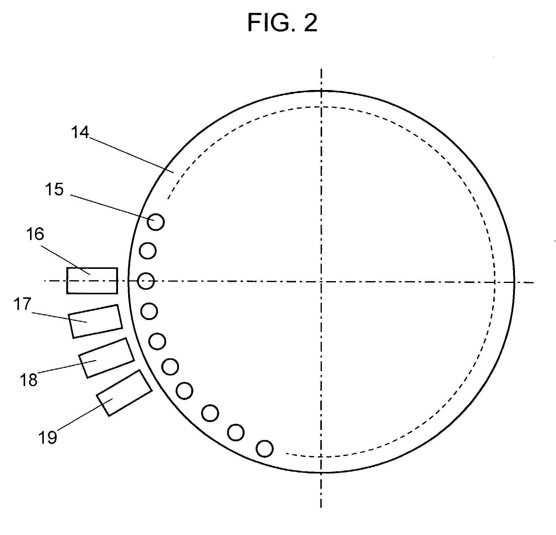
[0044]FIG. 2 illustrates the apparatus for ...

exemplary embodiment 2

[0052]The same elements used in the first embodiment are denoted with the same marks, and their descriptions are omitted here.

[0053]In FIG. 1, disc-shaped yoke 9—made of soft magnetic material and coaxial with the rotor—is disposed on a first side of coils 1–3, and rotor 8 is on a second side of coils 1–3. Yoke 9 has an area equal to or wider than the area the permanent magnet occupies. The permanent magnet attracts disc-shape yoke 9, and holing member 11 supports yoke 9. Printed circuit board 4 forming a stator is placed within an area spanning approximate 180 degree with regard to a rotary shaft of rotor 8 and includes coils 1, 2 and 3 assigned to respective 3 phases.

[0054]Being different from a conventional stator having two coils in each phase, the stator according to this invention has one coil in each phase. In the case when a number of turns of a coil and a thread diameter of the coil equal to those of a conventional coil, a total resisting value of respective phases is thus ...


PUM

PropertyMeasurementUnit
Angleaaaaaaaaaa
Mechanical strengthaaaaaaaaaa

Abstract

A plurality of motors are assembled. A plurality of part-sized stators are provided. Each of the part-sized stators is a split portion of a full-sized stator which has been previously split. The full-sized stator includes a printed circuit board with a plurality of coils. Each part-sized stator is inserted into a respective motor.

Description

[0001]THIS APPLICATION IS A CONTINUATION OF U.S. patent application Ser. No. 09 / 424,551 FILED JAN. 5, 2000 (abandoned) WHICH IS A NATIONAL PHASE OF PCT / JP99 / 01384 filed Mar. 19, 1999.TECHNICAL FIELD[0002]The present invention relates to a brushless motor and a manufacturing method of the same, and more particularly, relates to an arrangement of coils thereof.BACKGROUND ART[0003]Brushless motors demand a greater torque per unit-current (expressed with the motor constant “Kt”) in order to obtain a higher power with a small body. For this purpose, in a conventional motor, coils are generally arranged to occupy an area not less than the area a permanent magnet occupies so that a number of coils—represented by S—in each phase becomes greater. However, in a case of arranging number of flat air-core coils on a printed circuit board, the increasing of number “S” incurs a higher manufacturing cost as well as more steps of processing. As a result, expensive brushless motors of a poor producti...

Claims


Application Information

Patent Timeline
IPC IPC(8): H02K15/00H01F7/08H02K3/26H02K11/04H02K15/02H02K21/24
CPCH02K3/26H02K15/02H02K21/24H02K11/0073Y10T29/49009Y10T29/49789Y10T29/49798Y10T29/49073H02K11/33
Inventor FUKUSHIMA, SHINJIYAGI, KAZUEI
Owner PANASONIC CORP
Why Eureka
Try Eureka